ProForm 640 English Manual - Page 9
not overtighten the Nylon Locknut. You must
 |
View all ProForm 640 manuals
Add to My Manuals
Save this manual to your list of manuals |
Page 9 highlights
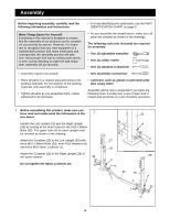
9. Lubricate the M10 x 136mm Bolt (22) and slide an M10 Washer (6) onto it. Push the Bolt through the indicated hole in the left Backrest Tube (53). Slide a Plastic Washer (21) onto the M10 x 136mm Bolt (22). Insert the Bolt into the hole in the left side of the "U"-bracket (E) on the Decline Carriage (11). Slide a Plastic Washer (21) onto the M10 x 136mm Bolt (22) and pull it back until it barely sticks through the "U"-bracket (E). Place the Seat (14) so that the Seat Carriage (16) is between the legs of the "U"-bracket. Push the M10 x 136mm Bolt (22) through the holes in the Seat Carriage. Note: It may be easier to perform this step if you tilt the Seat to a vertical position. 9 14 16 22 6 Lubricate 11 53 21 21 E Push a Plastic Washer (21) in between the Seat Carriage (16) and the right side of the "U"-bracket (E). Line up the Washer and the holes, then push the M10 x 136mm Bolt (22) through the Washer and the "U"Bracket. Slide a Plastic Washer (21) onto the M10 x 136mm Bolt (22). Refer to the inset drawing and make sure you have all parts in the right sequence. 22 6 53 21 16 21 53 6 1 E 10. Slide the indicated hole in the right Backrest Tube (53) onto the M10 x 136mm Bolt (22). 10 14 Slide an M10 Washer (6) onto the M10 x 136mm Bolt (22) and secure it with an M10 Nylon Locknut (1). Do not overtighten the Nylon Locknut. You must be able to freely pivot the Seat and Backrest Tubes. Insert the "L"-Pin (63) through one of the holes in the bracket (F) on the Seat Carriage (16). The "L"-Pin should be on top of the Decline Carriage (11). 22 53 11 16 F 63 6 1 11. Attach the Backrest (15) to the Backrest Tubes (53) 11 with four M6 x 38mm Screws (4) and four M6 Washers (50). 15 53 4 9 50 53 4 50
-
 1
1 -
2
-
3
-
 4
4 -
 5
5 -
 6
6 -
 7
7 -
 8
8 -
 9
9 -
 10
10 -
 11
11 -
 12
12 -
 13
13 -
 14
14 -
15
-
16
-
17
-
18
-
19
-
20
-
21
-
22
-
23
 |
 |
