ProForm 650 Cardio Cross Trainer Elliptical English Manual - Page 6
damaged during - battery
 |
View all ProForm 650 Cardio Cross Trainer Elliptical manuals
Add to My Manuals
Save this manual to your list of manuals |
Page 6 highlights
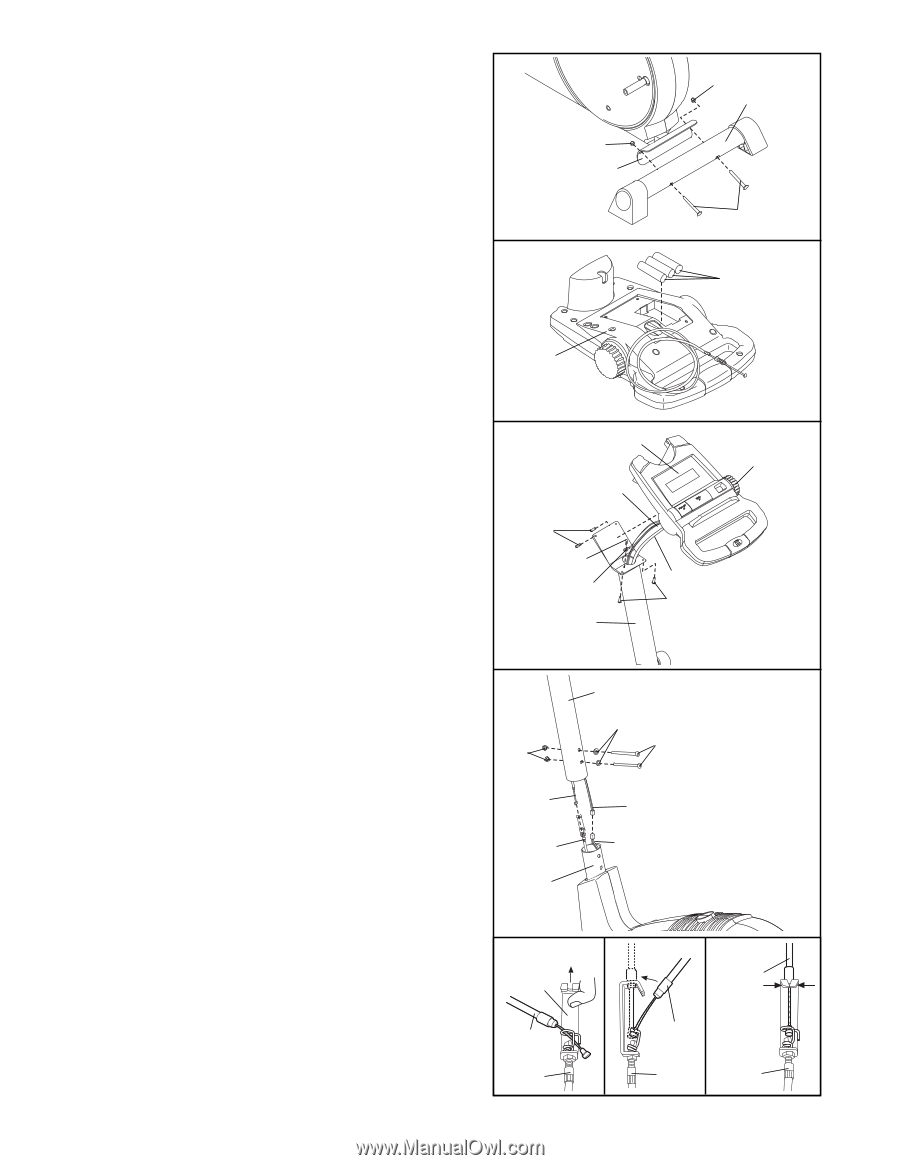
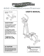
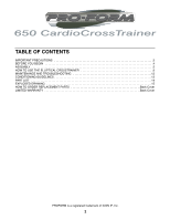
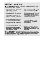
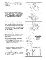
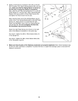
2. While another person lifts the back of the Frame (1), 2 attach the Rear Stabilizer (9) to the Frame with two M10 x 75mm Carriage Bolts (34) and two M10 Nylon Locknuts (33). 33 1 3. The Console (23) requires three "AA" batteries (not included); alkaline batteries are recommended. Insert three batteries into the battery compartment. Make sure that the batteries are oriented as shown by the diagram inside the battery compartment. 3 23 33 9 34 Batteries 4. While another person holds the Console (23) in the position shown, insert the control cable and the console wire down through the Upright (2). Attach the ground wire to the Upright with an M4 x 16mm Screw (52). Insert the excess cable and wire into the Upright. Attach the Console (23) to the Upright (2) with four M4 x 16mm Screws (52). Be careful to avoid pinching the cable and wires. Make sure that the Resistance Knob (42) is turned to the lowest setting before proceeding. 4 23 42 Console Wire 52 52 Ground Wire 2 Control Cable 52 5. While another person holds the Upright (2) in the position shown, connect the console wire to the Reed Switch Wire (53). Next, connect the control cable to the Resistance Cable (43) in the following way: • See drawing A. Pull up on the metal bracket, and insert the tip of the control cable into the wire clip on the Resistance Cable (43) as shown. • See drawing B. Firmly pull the control cable and slide it into the metal bracket on the Resistance Cable (43) as shown. • See drawing C. Using pliers, squeeze the prongs on the upper end of the metal bracket together. Push the excess cable and wires down into the Frame (1). Insert the Upright (2) into the Frame. Do not pinch the wires or cables. Secure the Upright to the Frame with two M10 x 76mm Button Bolts (7), two M10 Split Washers (45), and two M10 Nylon Locknuts (33). Do not tighten the Bolts yet. 6 5 33 Control Cable 43 1 A Metal Bracket Control Cable 43 2 45 Make sure the wires and cables do not get 7 pinched and damaged during this step. Console Wire 53 B C Control Cable Control Cable 43 43
-
 1
1 -
 2
2 -
 3
3 -
 4
4 -
 5
5 -
 6
6 -
 7
7 -
 8
8 -
 9
9 -
 10
10 -
 11
11 -
 12
12 -
13
-
14
-
15
-
16
 |
 |