ProForm 665 E Treadmill English Manual - Page 10
Console May Be Damaged When
 |
View all ProForm 665 E Treadmill manuals
Add to My Manuals
Save this manual to your list of manuals |
Page 10 highlights
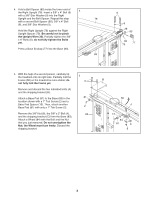
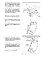
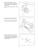
9. Set the Crossbar (39) on the console assembly. Tighten two 1/4" x 3/4" Bolts (5) with two 1/4" Star Washers (14) into the Crossbar. Start both Bolts but do not tighten them yet. Tighten four 1/2" Screws (1) into the Crossbar (39). Start all four Screws before tightening any of them. Note: Use the two 1/2" Screws from step 7. Tighten the two 1/4" x 3/4" Bolts (5) and the four 3/4" Screws (12) in the Right and Left Handrails (90, 88). 9 90 5 14 1 39 1 5 14 88 12 10. Slide the Left Handrail Spacer (96) and the Right Handrail Spacer (97) onto the top of the 10 Left Upright (74) and Right Upright (78). 96 12 Console Assembly 74 11. Have a second person hold the console assembly near the Right Upright (78) and Left Upright (not shown). Connect the Upright Wire (38) to the console wire. See the inset drawing. The connectors should slide together easily and snap into place. If they do not, turn one connector and try again. IF THE CONNECTORS ARE NOT CONNECTED PROPERLY, THE CONSOLE MAY BE DAMAGED WHEN YOU TURN ON THE POWER. Remove the wire tie from the Upright Wire (38). Insert the connectors and the excess wire into the Right Handrail (90). Set the console assembly on the Right Handrail Spacer (97) and Left Handrail Spacer (not shown). Be careful not to pinch the wires. 11 90 Wire Tie 10 97 78 Console Assembly Console Wire 38 97 Console 78 Wire 38
-
 1
1 -
2
-
3
-
4
-
 5
5 -
 6
6 -
 7
7 -
 8
8 -
 9
9 -
 10
10 -
 11
11 -
 12
12 -
 13
13 -
 14
14 -
 15
15 -
16
-
17
-
18
-
19
-
20
-
21
-
22
-
23
-
24
-
25
-
26
-
27
-
28
-
29
-
30
-
31
-
32
 |
 |
