ProForm 665 E Treadmill English Manual - Page 9
Orient the Left Upright 74 and the Left Upright
 |
View all ProForm 665 E Treadmill manuals
Add to My Manuals
Save this manual to your list of manuals |
Page 9 highlights
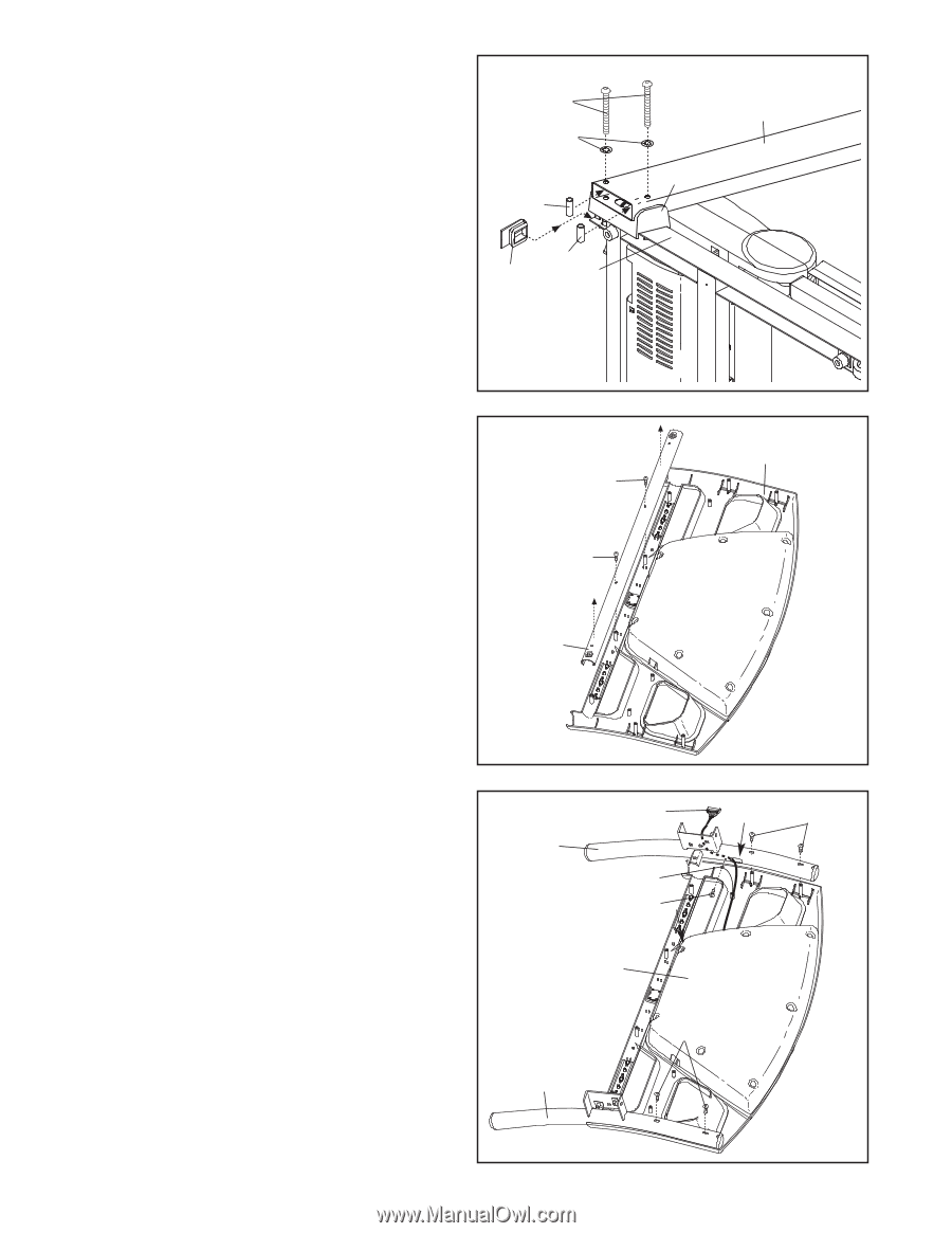
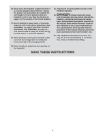
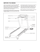
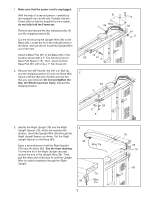
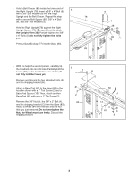
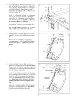
6. Hold a Bolt Spacer (80) inside the lower end of the Left Upright (74). Insert a 3/8" x 4" Bolt (6) with a 3/8" Star Washer (9) into the Left Upright and the Bolt Spacer. Repeat this step with a second Bolt Spacer (80), 3/8" x 4" Bolt (6), and 3/8" Star Washer (9). Orient the Left Upright (74) and the Left Upright Spacer (76) as shown. Hold the Left Upright Spacer and the Left Upright against the Base (83). Partially tighten the two 3/8" x 4" Bolts (6); do not fully tighten the Bolts yet. Press a Base Endcap (77) into the Base (83). With the help of a second person, tip the treadmill so that the Base (83) is flat on the floor. 6 6 9 80 80 77 83 7. Set the console assembly face down on a soft surface to avoid scratching the console assem- 7 bly. Remove the two 1/2" Screws (1) from the Crossbar (39), and then remove the Crossbar. Save the two Screws and the Crossbar for step 9. 1 1 74 76 Console Assembly 39 8. Identify the Right Handrail (90), which has a 8 large hole in the location shown. Hold the Right Console Wire Handrail near the console assembly. Attach the console ground wire to the Right Handrail with a 90 #8 x 1/2" Ground Screw (87). Ground Wire Hole 12 Insert the end of the console wire into the large hole in the Right Handrail (90) and out of the top as shown; use needlenose pliers if necessary. Attach the Right Handrail with two 3/4" Screws (12). Make sure that no wires are pinched. Start both Screws but do not tighten them yet. 87 Console Assembly 12 Attach the Left Handrail (88) to the console as- sembly with two 3/4" Screws (12). Start both 88 Screws but do not tighten them yet. 9
-
 1
1 -
2
-
3
-
 4
4 -
 5
5 -
 6
6 -
 7
7 -
 8
8 -
 9
9 -
 10
10 -
 11
11 -
 12
12 -
 13
13 -
 14
14 -
15
-
16
-
17
-
18
-
19
-
20
-
21
-
22
-
23
-
24
-
25
-
26
-
27
-
28
-
29
-
30
-
31
-
32
 |
 |