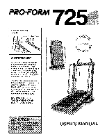
ProForm 725xt Treadmill English Manual - Page 5
Assembly
 |
View all ProForm 725xt Treadmill manuals
Add to My Manuals
Save this manual to your list of manuals |
Page 5 highlights
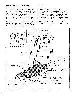
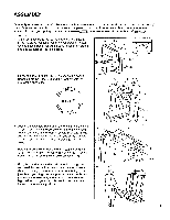
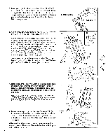
ASSEMBLY Assembly requires two people. Set the treadmill in a cleared area and remove all packing materials. Do not dis- pose of the packing materials until assembly is completed. Tools required for assembly: The included alien wrench and your phillips screwdriver and two adjustable wrenches ,S;==rO • ,MM 1. Attach six Base Pads (73) to the bottom of the Base (75) in the indicated locations (see the inset drawing). Note: One additional Base Pad will be used in assembly step 6, and one extra Base Pad is included. 73 ..... 73 73 i -... ..... ,...... 75 0 ...i...- 73 2. Firmly hold the Uprights (11, 58) as shown. Raise the Uprights until the Base (75) and the front Wheels (74) 2 11 are resting on the floor. APR 2 6 1996 * 74, 3. Loosen the Crossbar Bolts (2) in the ends of the Console Crossbar (17). Pivot the Console (6) to the angle shown. Look under the Left and Right Crossbar Brackets (4, 51) and find the two small holes in each end of the Console Crossbar (17). Tighten Crossbar Screws (9) into all four holes. Rotate the Console (6) upward until it stops. Using the 7/32" end of the Allen Wrench (56), tighten the Crossbar Bolts (2) in the ends of the Console Crossbar (17). 4. Next, the treadmill should be raised to the storage position. Hold the treadmill with your hands in the locations shown at the right. To decrease the possibility of injury, bend your legs and keep your back straight. As you raise the treadmill, make sure to lift with your legs rather than your back. Raise the treadmill about halfway to the vertical position. 3 2 4 , -- 9 17 4 ( til 58 74 75 6 - G) 2 51 .-. .-- 9 56 i 5
-
 1
1 -
 2
2 -
 3
3 -
 4
4 -
 5
5 -
 6
6 -
 7
7 -
 8
8 -
 9
9 -
 10
10 -
 11
11 -
12
-
13
-
14
-
15
-
16
-
17
-
18
-
19
 |
 |
