ProForm 725xt Treadmill English Manual - Page 6
location.Tip
 |
View all ProForm 725xt Treadmill manuals
Add to My Manuals
Save this manual to your list of manuals |
Page 6 highlights
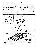
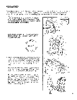
5. Move your right hand to the position shown at the right, and hold the treadmill firmly. Using your left hand, lift the storage latch. Raise the treadmill until the locking pin snaps into the storage latch. Make sure that the locking pin Is inside the storage latch, and that the storage latch is fully closed. 5 Storage Latch , Locking Pin 6. See drawing 6B. Attach a Base Pad (73) to the bottom of the Stabilizer Plate (88) in the indicated location. 6A See drawing 6A. Stand behind the treadmill. Hold the Left Crossbar Bracket (4) and the Right Crossbar Bracket (not shown). Place one foot on the Base (75) in the indicated location.Tip the treadmill back slightly. While the treadmill is held in this position, a second person should slide the Stabilizer Plate (88) onto the Base (see drawing 6C). Keeping your foot on the Base, carefully tip the treadmill up until it is resting on the Base. Make sure that the Stabilizer Plate (88) stays on the Base. See drawing 6C. Attach the Stabilizer Plate (88) to the Base (75) with a Stabilizer Plate Bolt (105), two Washers (97), and the Stabilizer Plate Nut (95) as shown. % 6B 4 88 , . 73 9 ' 88 75 6C ,..--' 95 97 105 7. Refer to assembly drawing 5 at the top of this page. Hold the upper end of the treadmill with your right hand as 7 shown. Using your left hand, lift the storage latch. Pivot the treadmill slightly until the locking pin is out of the stor- age latch. Hold the treadmill firmly with both hands, and lower the treadmill to the floor. To decrease the possibility of injury, bend your legs and keep your back straight. 75 88 rI 8. Remove the paper backing from the Adhesive Clip (44). Press the Adhesive Clip onto the Frame (84) in the indi- 8 cated location. Press the Allen Wrench (57) into the Adhesive Clip. The use of the Allen Wrench is described 44 on page 13. Make sure that all parts are tightened before you use the treadmill. Note: Place a mat beneath the treadmill to protect the floor or carpet. 57 84 6
-
 1
1 -
 2
2 -
 3
3 -
 4
4 -
 5
5 -
 6
6 -
 7
7 -
 8
8 -
 9
9 -
 10
10 -
 11
11 -
 12
12 -
13
-
14
-
15
-
16
-
17
-
18
-
19
 |
 |
