ProForm 750cs English Manual - Page 6
Assembly - lubricant
 |
View all ProForm 750cs manuals
Add to My Manuals
Save this manual to your list of manuals |
Page 6 highlights
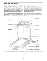
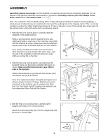
ASSEMBLY Assembly requires two people. Set the treadmill in a cleared area and remove all packing materials. Do not dispose of the packing materials until assembly is completed. Assembly requires your own Phillips screw- driver and rubber mallet . Note: The underside of the treadmill walking belt is coated with high-performance lubricant. During shipping, a small amount of lubricant may be transferred to the top of the walking belt or the shipping carton. This is a normal condition and does not affect treadmill performance. If there is lubricant on top of the walking belt, simply wipe off the lubricant with a soft cloth and a mild, non-abrasive cleaner. 1. With the help of a second person, carefully raise the treadmill to the upright position. 1 While a second person tips the treadmill to one side slightly and holds it, insert one of the Extension Legs (103) 82 into the treadmill as shown. Make sure that the Extension Leg is turned so the Thick Base Pad (97) is on the bottom. 103 Next, tip the treadmill to the other side and insert the other Extension Leg (not shown) in the same way. Lower the side of the treadmill so that both Extension Legs (103) are resting flat on the floor. 97 2. With the help of a second person, carefully lower the treadmill frame and then tip the Uprights (82) down as 2 shown. Make sure that the Extension Legs (103) re- main in the Uprights. Attach each Extension Leg (103) with two Screws (101) and a Base Pad (120) as shown. Note: One replacement Base Pad (120) and Spacer (not shown) may be included. If a Base Pad becomes worn and needs to be replaced, use the replacement Base Pad. If a Thick Base Pad (97) needs to be replaced, use the replacement Base Pad with the Spacer. 82 3. With the help of a second person, carefully tip the Uprights (82) back to the vertical position. 3 Attach the Latch Assembly (9) to the left Upright (82) with the two 1/2" Screws (89). 97 120 101 103 97 89 9 120 101 103 97 101 82 89 6
-
 1
1 -
 2
2 -
 3
3 -
 4
4 -
 5
5 -
 6
6 -
 7
7 -
 8
8 -
 9
9 -
 10
10 -
 11
11 -
 12
12 -
13
-
14
-
15
-
16
-
17
-
18
-
19
-
20
-
21
-
22
-
23
-
24
-
25
-
26
 |
 |
