ProForm 890e English Manual - Page 6
adjustable
 |
View all ProForm 890e manuals
Add to My Manuals
Save this manual to your list of manuals |
Page 6 highlights
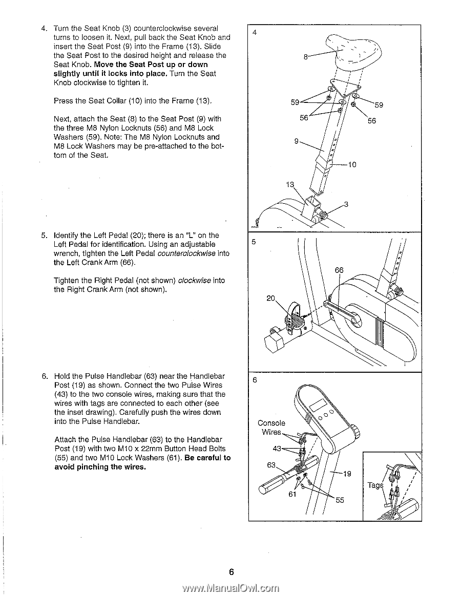
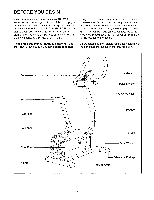
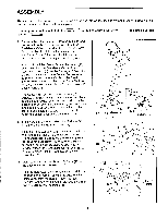
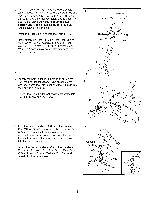
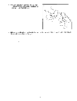
4. Turn the Seat Knob (3) counterclockwise several 4 turns to loosen it. Next, pull back the Seat Knob and insert the Seat Post (9) into the Frame (13). Slide the Seat Post to the desired height and release the Seat Knob. Move the Seat Post up or down slightly until it locks into place. Turn the Seat Knob clockwise to tighten it. Press the Seat Collar (10) into the Frame (13). Next, attach the Seat (8) to the Seat Post (9) with the three M8 Nylon Locknuts (56) and M8 Lock Washers (59). Note: The M8 Nylon Locknuts and M8 Lock Washers may be pre-attached to the bottom of the Seat. 8 59 56 9 13 ,,. o 0 0 o 10 3 5. Identify the Left Pedal (20); there is an "L" on the Left Pedal for identification. Using an adjustable wrench, tighten the Left Pedal counterclockwise into the Left Crank Arm (66). Tighten the Right Pedal (not shown) clockwise into the Right Crank Arm (not shown). 5 20 66 0 6. Hold the Pulse Handlebar (63) near the Handlebar Post (19) as shown. Connect the two Pulse Wires (43) to the two console wires, making sure that the wires with tags are connected to each other (see the inset drawing). Carefully push the wires down into the Pulse Handlebar. Attach the Pulse Handlebar (63) to the Handlebar Post (19) with two M10 x 22mm Button Head Bolts (55) and two M10 Lock Washers (61). Be careful to avoid pinching the wires. 6 Console Wires 43 63 61 N 19 55 Tags 6
-
 1
1 -
 2
2 -
 3
3 -
 4
4 -
 5
5 -
 6
6 -
 7
7 -
 8
8 -
 9
9 -
 10
10 -
 11
11 -
 12
12 -
13
-
14
 |
 |