ProForm Xp 690t Treadmill User Manual - Page 11
Start both Washer Head Screws
 |
View all ProForm Xp 690t Treadmill manuals
Add to My Manuals
Save this manual to your list of manuals |
Page 11 highlights
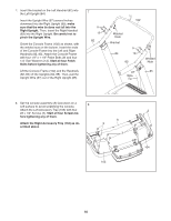
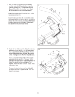
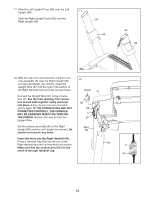
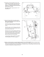
9. With the help of a second person, hold the handrail assembly (B) upside-down near the console assembly (A). Connect the Console Ground Wires (6) in the handrail assembly to the ground wires in the console assembly. Insert the console wire (C) into the track in the console assembly (A). Insert the Ground Wires (6) into the hole in the console assembly (A) as you set the handrail assembly (B) in the console assembly. Make sure that the console wire (C) stays in the track. Be careful not to pinch any wires. 9 A 6 B 102 C Track Ground Wires 10. Attach the handrail assembly (B) to the console assembly (A) with two #8 x 3/4" Washer Head Screws (2). Start both Washer Head Screws before tightening either of them. Be careful not to overtighten the Washer Head Screws. Attach a Console Clamp (105) to the console assembly (A) with two #8 x 1" Screws (107). Start both Screws before tightening either of them. Be careful not to overtighten the Screws. Attach the other Console Clamp (105) in the same way. Remove the wire ties from the Handrails (82, 83). Press the 5/16" Cage Nuts (38) back into place, if necessary. 10 2 38 82 83 2 B 38 A 107 107 105 105 11
-
 1
1 -
2
-
3
-
4
-
5
-
 6
6 -
 7
7 -
 8
8 -
 9
9 -
 10
10 -
 11
11 -
 12
12 -
 13
13 -
 14
14 -
 15
15 -
 16
16 -
17
-
18
-
19
-
20
-
21
-
22
-
23
-
24
-
25
-
26
-
27
-
28
-
29
-
30
-
31
-
32
 |
 |
