Reebok 825 English Manual
Reebok 825 Manual
 |
View all Reebok 825 manuals
Add to My Manuals
Save this manual to your list of manuals |
Reebok 825 manual content summary:
- Reebok 825 | English Manual - Page 1
there are missing or damaged parts, we will guarantee complete trained technicians on our customer hot line will provide immediate assistance, free of charge to you. CUSTOMER HOT LINE: 1-800-999-3756 Mon.ÐFri., 6 a.m.Ð6 p.m. MST CAUTION Read all precautions and instructions in this manual - Reebok 825 | English Manual - Page 2
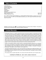
CHART are attached in the center of this manual. Remove the PART LIST/EXPLODED DRAWING and the PART IDENTIFICATION CHART before beginning assembly. REEBOK and the Vector Logo are registered trademarks and service marks of Reebok. This product is manufactured and distributed under license - Reebok 825 | English Manual - Page 3
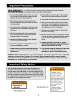
training system are adequately informed of all precautions. 2. Read all instructions in this manual and in the accompanying literature before using the training system of 12 and pets away from the training system at all times. 9. Keep hands and feet away from moving parts. 10. Make sure the cables - Reebok 825 | English Manual - Page 4
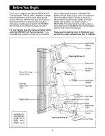
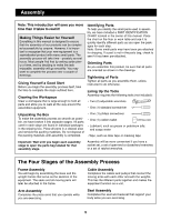
found on a decal attached to the REEBOK¨ 825 Training System (see the front cover of this manual). Please use the drawing below to familiarize yourself with the major parts and how they fit together. Shroud Covering Weight Stack Backrest Adjustment Tube Weight Stack ASSEMBLED DIMENSIONS: Height: 81 - Reebok 825 | English Manual - Page 5
this manual is small parts. Parts As you assemble this product, be sure that all parts are oriented as shown in the drawings. Tightening of Parts Tighten all parts as you assemble them, unless instructed to open the parts bag labeled for that moving parts will weights. This ties the different parts - Reebok 825 | English Manual - Page 6
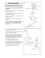
Frame Assembly 1 1. Before beginning assembly, make sure you have read and understood the information on page 5. Locate and open the parts bag labeled ÒFRAME ASSEMBLY.Ó Support Tube Press a 2Ó Square Inner Cap (33) into each open tube on the Press Frame (12). Press a 2Ó Square Inner Cap (33) - Reebok 825 | English Manual - Page 7
4 5 1/2Ó Bolt (57) and a 3/8Ó Nylon Locknut (50). 8 80 78 11 6 7 57 50 4 5. Place two Weight Bumpers (19) over the indicated 5 holes in the Stabilizer (5). Insert the two Weight Guides (23) through the Weight 23 23 Bumpers (19) and the holes in the Stabilizer (5). Attach the indicated - Reebok 825 | English Manual - Page 8
Bolt yet. Attach the Weight Guides (23) to the Top Frame (1) with two 3/8Ó x 1 3/4Ó Bolts (60) and two 3/8Ó Nylon Locknuts (50). Go back and fully tighten all Nylon Locknuts used in steps 1, 2 and 6. 36 26 Holes Large Pin Groove 77 26 Cable Assembly 7. Locate and open the parts - Reebok 825 | English Manual - Page 9
8. Remove the upper of the two 3/8Ó x 3Ó Bolts (45) attaching the Top Frame (1) to the Main Upright (3). Feed the bolt on the High Cable (73) through the indicated slot in the Main Upright (3) in the direction shown. Note: Follow the procedure described in step 7 for attaching all Pulleys. Wrap the - Reebok 825 | English Manual - Page 10
(55), two Pulley Bushings (42) and a 3/8Ó Nylon Jamnut (63). Thread the bolt on the High Cable (73) a couple of turns into the top of the Weight Tube (36) as shown in the inset drawing. 13 63 42 35 55 42 63 Slot B 1 73 55 42 55 Bolt 73 35 Slot A 42 - Reebok 825 | English Manual - Page 11
14. The Low Cable (72) is the only remaining Cable. It is approximately 206Ó long. Note that it has a large ball on one end and a small ball on the other. Route the smaller ball on the Low Cable (72) through the indicated slots in the Leg Lever (29) and the front leg on the Base (8). Attach a 4Ó - Reebok 825 | English Manual - Page 12
the High Cable to complete this step. Doing so will lift the Top Weight off the Weight Stack, and it will be helpful to have a second person hold the tightening both Cables (73 and 72, not shown). Thread the bolt into the Weight Tube until both Cables are tight and rest firmly in the grooves of all - Reebok 825 | English Manual - Page 13
Arm Assembly 20 20. Note: Some of the parts used in arm assembly are located in the parts bag labeled ÒSeat Assembly.Ó 50 Attach the Press Arm (46) to the Press Frame (12) with two 3/8Ó x 3Ó Bolts (45) and two 3/8Ó Nylon Locknuts (50). 12 - Reebok 825 | English Manual - Page 14
23. Press a 1Ó x 2Ó Inner Cap (43) into each end of the Backrest Frame (15). Attach the Backrest (41) to the Backrest Frame (15) with four 1/4Ó x 3/4Ó Bolts (17). Press a 3/4Ó Round Inner Cap (34) into each end of the pad tube on the Backrest Frame (15). Slide a Leg Foam Roller (74) onto each end of - Reebok 825 | English Manual - Page 15
the remaining parts will be explained in ADJUSTMENT, beginning on page 17 of this manual. Before using the training system, pull each cable a few times to be sure that the cables move smoothly over the pulleys. If one of the cables does not move smoothly, find and correct the problem. IMPORTANT: If - Reebok 825 | English Manual - Page 16
routed correctly, that the Pulleys move smoothly and that the Cable Traps do not touch or bind the Cables. Incorrect cable routing can damage the weight system. 82 9 1 4 High Cable (73) 6 3 7 5 4 6 10 Cable ID Chart 5 3 Low Cable (72) 72 73 16 2 1 Large Ball - Reebok 825 | English Manual - Page 17
Adjustment The instructions below describe how each part of the training system can be adjusted. Refer to the exercise guide accompanying this manual to see how the training system should be set up for each exercise. IMPORTANT: When attaching the lat bar, row bar, ankle strap or ab strap, make sure - Reebok 825 | English Manual - Page 18
Adjusting the Position of the Backrest To adjust the position of the Backrest (41), unscrew the handle of the Adjustment Knob (9) until it is loose. Pull out the handle as far as it will go and slide the Backrest Frame (15, not visible) to the desired position. Release the handle until the Knob - Reebok 825 | English Manual - Page 19
Trouble-shooting and Maintenance Inspect and tighten all parts each time you use the training system. Replace any worn parts immediately. The training system can be cleaned using a damp cloth and mild non-abrasive detergent. Do not use solvents. Tightening the Cables Woven cable, the type of cable - Reebok 825 | English Manual - Page 20
1 3/4Ó Square Inner Cap (21) 3/4" Round Inner Cap (34) 2" x 3Ó Inner Cap (24) 2" Square Inner Cap (33) 1" x 2Ó Inner Cap (43) - Reebok 825 | English Manual - Page 21
Part Identification ChartÑRBSY82580 R1198A 1/4" Nylon Jamnut (51 ) 1/4" Nylon Locknut (25) 5/16" Nylon Locknut (81) 5/16" Nylon Jam Nut (93) 5/16" Flat Washer (8) 1/4" Flat Washer (71) 1/4" x 1 1/2" - Reebok 825 | English Manual - Page 22
3/8" Nylon Jam Nut (63) 3/8" Nylon Locknut (50) 3/8" Flat Washer (55) 3/8" x 8" Bolt (59) 3/8" x 1 3/4" Bolt (60) 3/8" x 2" Bolt (62) 3/8" x 2 1/2" Bolt (54) 3/8" x 3" Bolt (45) 3/8" x 4" Bolt (65) 3/8" x 3 3/4" Carriage Bolt (52) 3/8" x 5 1/2" Bolt (57) Pulley Bushing (42) - Reebok 825 | English Manual - Page 23
Bar 1/4Ó Flat Washer Low Cable High Cable Leg Foam Roller Ab Strap 5 7/8Ó Long Bushing Weight Insert 5/16Ó x 3Ó Bolt 5/16Ó Nylon Jamnut 5/16Ó Flat Washer 5/16Ó Nylon Locknut UserÕs Manual Exercise Guide Note: Ò#Ó indicates a non-illustrated part. Specifications are subject to change without notice. - Reebok 825 | English Manual - Page 24
Exploded DrawingÑModel No. RBSY82580 25 17 71 71 17 33 33 23 42 42 35 35 42 35 42 58 58 35 42 42 45 54 61 70 58 18 18 63 27 53 42 55 1 63 55 63 50 50 42 42 55 55 73 55 54 14 43 18 63 59 53 58 55 54 55 63 54 55 63 17 14 24 60 42 35 63 55 42 42 73 31 35 - Reebok 825 | English Manual - Page 25
The NAME of the product (Reebok¨ 825 Training System). 3. The SERIAL NUMBER of the product (see the front cover of this manual). 4. The KEY NUMBER and DESCRIPTION of the part(s) (see the PART LIST and EXPLODED DRAWING attached at the center of this manual). Weight Resistance Chart This chart shows
-
 1
1 -
 2
2 -
 3
3 -
 4
4 -
 5
5 -
 6
6 -
 7
7 -
8
-
9
-
10
-
11
-
12
-
13
-
14
-
15
-
16
-
17
-
18
-
19
-
20
-
21
-
22
-
23
-
24
-
25
 |
 |

CAUTION
Read all precautions and instruc-
tions in this manual before using
this equipment. Save this manual
for future reference.
USER°S MANUAL
Model No. RBSY82580
Serial No.
The serial number is found in the
location shown below. Write the
serial number in the space above.
QUESTIONS?
As a manufacturer, we are
committed to providing complete
customer satisfaction. If you
have questions, or if there are
missing or damaged parts, we
will guarantee complete satisfac-
tion through direct assistance
from our factory.
TO AVOID UNNECESSARY
DELAYS, PLEASE CALL DIRECT
TO OUR TOLL-FREE CUSTOMER
HOT LINE. The trained techni-
cians on our customer hot line
will provide immediate assis-
tance, free of charge to you.
CUSTOMER HOT LINE:
1-800-999-3756
Mon.—Fri., 6 a.m.—6 p.m. MST
PATENT PENDING
Serial Number Decal