Rheem P-M406 Operating Instructions
Rheem P-M406 Manual
 |
View all Rheem P-M406 manuals
Add to My Manuals
Save this manual to your list of manuals |
Rheem P-M406 manual content summary:
- Rheem P-M406 | Operating Instructions - Page 1
a neighbor's phone. Follow the gas sup- plier's instructions. • If you cannot reach your gas supplier, call the fire department. Installation and service must be performed by a qualified installer, service agency or the gas supplier. This manual should be maintained in legible condition and kept - Rheem P-M406 | Operating Instructions - Page 2
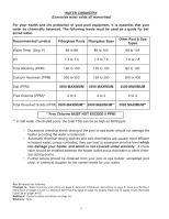
be chemically balanced. The following levels must be used as a guide for balanced water. Recommended Level(s) Fiberglass Pools Fiberglass Spas Other Pool to: Water chemistry instructions on page 2, Automatic Chlorinator instructions on page 8, Hurricane Tie-Down instructions on pages 13 and - Rheem P-M406 | Operating Instructions - Page 3
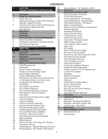
SERVICING INSTRUCTIONS 4 SECTION 1 31 General Location of Controls START-UP PROCEDURES 32 Control Panel Removal 4 Before Start-Up 32 Control Adjustments - AFT Models 5 Lighting Instructions & Shut-Off Procedures - 32 Control Adjustments - Millivolt Models Manually Tables TROUBLESHOOTING - Rheem P-M406 | Operating Instructions - Page 4
- READ BEFORE OPERATING WARNING: IF YOU DO NOT FOLLOW THESE INSTRUCTIONS EXACTLY, A FIRE OR EXPLOSION MAY RESULT, CAUSING PROPERTY DAMAGE, commercial applications, are also available. This manual provides installation, operation, maintenance, and service information for these heaters. ON OFF If - Rheem P-M406 | Operating Instructions - Page 5
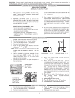
exercised when lighting propane heaters. LIGHTING INSTRUCTIONS AND SHUT-OFF PROCEDURES MILLIVOLT SYSTEM (MANUALLY LIGHTED PILOT) A. This appliance has 9. If knob does not pop up when released, stop and immediately call your service technician or gas supplier. 10. Stand to the side of the heater and - Rheem P-M406 | Operating Instructions - Page 6
to the appliance. 11. Set thermostat to desired setting. 12. If the appliance will not operate, follow the instructions "To Turn Off Gas To Appliance" GAS INLET and call your service technician or gas supplier. SHUT-OFF PROCEDURES 1. Set the thermostat at the lowest setting. to "Off". Make - Rheem P-M406 | Operating Instructions - Page 7
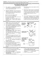
qualified service person at the time of installation and periodically checked thereafter. Refer to Pressure Switch Adjustment on pg. 38 of this manual). a medical history of heart disease, circulatory problems, diabetes, or blood pressure problems should obtain a physician's advice before using - Rheem P-M406 | Operating Instructions - Page 8
occur, shut the heater off and contact your gas supplier or qualified service agency. 5. On indoor heaters, clean room intake openings to ensure have electrical power but the heater will not fire check the following or see Troubleshooting section: 1. The time clock must be in the "ON" position. The - Rheem P-M406 | Operating Instructions - Page 9
outdoors in freezing climate areas may be shut down for the winter. Observe the following procedure for winterizing the heater: 1. Turn off gas valve, manual gas valve, and electrical supply to the heater. 2. Open drain plug located on the inlet/outlet header, (under water pipes). Remove the heat - Rheem P-M406 | Operating Instructions - Page 10
PART TWO INSTALLATION AND SERVICE INSTRUCTIONS SECTION 1 - RECEIVING EQUIPMENT The manufacturer recommends that this manual be reviewed thoroughly before installing your pool/spa heater. If there are any questions that this manual does not answer, please contact the factory or your local - Rheem P-M406 | Operating Instructions - Page 11
license. Persons not qualified shall not attempt to fix this equipment nor attempt repairs according to these instructions. WARNING: Improper installation, adjustment, alteration, service or maintenance may damage the equipment, create a hazard resulting in asphyxiation, explosion or fire, and will - Rheem P-M406 | Operating Instructions - Page 12
recommend a clearance of at least 24" in the front, and at least 18" on the water connection side. This will enable the heater to be serviced in its installed location, that is, without movement or removal of the heater. Clearances less than these (6" minimum), may require removal of the heater to - Rheem P-M406 | Operating Instructions - Page 13
Heaters must not be installed under an overhang of less than three 3 ft from the top of the heater. Three sides must be open in the area under the overhang. Roof water drainage must be diverted away from the heaters installed under overhangs with the use of gutters. For U.S. installations, the point - Rheem P-M406 | Operating Instructions - Page 14
FLORIDA AND TEXAS BUILDING CODES WIND SPEED = 150 MPH, 3 SECOND GUST EXPOSURE = C 206/266/336/406 Atmospheric MODEL # B 206 20" B 266 23" 336 26" 406 29" 40" 2" x 6" x 1/8" Pallet Anchor Bracket (4 Total) (Kit# 011636) 28" 3" Min. Conc. Pad by others 1/4" x 1-3/4" S.S. Tapcon Bolt & - Rheem P-M406 | Operating Instructions - Page 15
Clips INDOOR STACK KIT INCLUDES: (1) Drafthood, unpainted (1) Adapter plate (3) Mounting brackets (clips) (3) Screws (1) Instructions Clips Model 206A/207A 266A/267A 336A/337A 406A/407A OUTDOOR STACK Part No. 009834 009835 009836 009837 INDOOR STACK Part No. 009838 009839 009840 - Rheem P-M406 | Operating Instructions - Page 16
" 9" 64-9/16" 14.5" 12-1/8" 3/4" 2" 249 268 21 Designation for an AFT heater using propane gas is "EP"; an AFT heater using natural gas is "EN". Designation for a Millivolt heater using propane gas is "MP"; a Millivolt heater using natural gas is "MN". Prefix "C" is for cast iron (ASME) headers - Rheem P-M406 | Operating Instructions - Page 17
for cast iron (ASME) headers; "P" is for plastic (polymer) headers. Suffix "X" is for cupro-nickel tubing; "C" is for copper tubing. EXAMPLE: P-R407A-EN-X = Plastic headers, 407 model size, AFT, natural gas, cupro-nickel. For altitudes above 5,000 ft., consult the factory. For Canada, no de-rating - Rheem P-M406 | Operating Instructions - Page 18
have a minimum of 1/4 in. per ft rise and should be supported at not more than five foot intervals. Plumbers tape, criss-crossed, will serve . Optional Raypak D-2 Power Vent For more information consult the D-2 Power Vent manual, (Catalog No. 6000.57.1). The power vent assembly is a fan-assisted - Rheem P-M406 | Operating Instructions - Page 19
the vent stack or chimney must not rest on heater drafthood. Support must be provided in compliance with applicable codes. The heater Dissipate test pressure in the gas supply line before reconnecting the heater and its manual shut off valve to gas supply line. FAILURE TO FOLLOW THIS PROCEDURE MAY - Rheem P-M406 | Operating Instructions - Page 20
). ELECTRONIC IGNITION GAS VALVES-CONTINUED Gas Pressure Adjustment Robertshaw 7200 (Heater Model 206) Robertshaw 7000 BDER (Heater Models 266-336) MANUAL SHUT-OFF VALVE UNION Gas Pressure Adjustment Robertshaw 7000 DERHC (Heater Model 406) Non-Adjustable Gas Valve MANOMETER GAS PRESSURE TEST - Rheem P-M406 | Operating Instructions - Page 21
FLOW RATES MODEL 206/207 266/267 336/337 406/407 PIPE SIZE 1-1/4"-1-1/2" - 2" 1-1/4"-1-1/2" - 2" 1-1/4"-1-1/2" - 2" 1-1/4"-1-1/2" - 2" MIN. GPM 20 25 35 40 MAX. GPM* 125 125 125 125 *When flow rates exceed maximum GPM an external auxiliary bypass valve is required. See external bypass valve - Rheem P-M406 | Operating Instructions - Page 22
POLYMER HEADERS (STANDARD MODELS) Before attaching the 2-inch unions to the inlet/outlet header, make sure the O-rings are properly seated in the grooves. Use AquaLube or equivalent non-petroleum-based lubricant on the O-ring. Hand tighten the unions. Glue PVC piping directly to the unions. INLET/ - Rheem P-M406 | Operating Instructions - Page 23
INTERNAL AUTOMATIC BYPASS VALVE PRESSURE RELIEF VALVE INSTALLATION In addition to the Unitherm Governor, a built-in automatic bypass valve is provided in the in/out header. While the Unitherm Governor responds to the changes in water temperature in the heater, the internal bypass valve - Rheem P-M406 | Operating Instructions - Page 24
PLUMBING-WATER CONNECTIONS Single Pool Heater Installation Multiple Pool Heater Installation The heater requires water flow and positive pressure to fire and operate properly. It must therefore be installed downstream of the discharge side of the filter pump. A typical installation is plumbed as - Rheem P-M406 | Operating Instructions - Page 25
HEAT EXCHANGER REVERSAL PROCEDURE - STANDARD MODELS 1. Remove right and left side access panels (Figure 1). 2. Disconnect wires at high limit, AGS (automatic gas shut-off), and pressure switch on the in/out header (Figure 2). 3. AFT Models: Remove the thermostat temperature sensor by loosening the - Rheem P-M406 | Operating Instructions - Page 26
Heaters are factory-wired for 240 VAC power sup- ply. DO NOT attempt to operate at 208 VAC. NOTE: See page 38 for further instructions if using a time clock/fireman's switch. OPTION LOCATION LEFT SIDE FIELD WIRING CONTROL BOX (FACTORY MOUNTED LOCATION) The standard field-wiring connection is on - Rheem P-M406 | Operating Instructions - Page 27
fireman's switch connection or using a two or three-wire remote. See pages 36-38. If using a switched GFCI power source, the heater could display false service indicators on the display panel if the pump is turned off. 27 - Rheem P-M406 | Operating Instructions - Page 28
WIRING DIAGRAM - MILLIVOLT (MECHANICAL THERMOSTAT) 28 - Rheem P-M406 | Operating Instructions - Page 29
WIRING DIAGRAM - ATMOSPHERIC 29 - Rheem P-M406 | Operating Instructions - Page 30
WIRING DIAGRAM - LO NOx 30 - Rheem P-M406 | Operating Instructions - Page 31
SECTION 4 - SERVICING INSTRUCTIONS GENERAL LOCATION OF CONTROLS ATMOSPHERIC Drain Plug (Located in rear header) AFT Thermostat Circuit Board Roll-Out Switch Gas Valve Pilot LO NOx Drain Plug (Located in rear header) Blower Hose AFT Thermostat Circuit Board Roll-Out Switch (Manual) Blower Gas - Rheem P-M406 | Operating Instructions - Page 32
CONTROL PANEL REMOVAL 1. Remove screw from front door. Set aside door for serviceability. CONTROL ADJUSTMENTS - MILLIVOLT MODELS The water temperature is controlled by the heater thermostat on the upper front panel of the heater. The control center contains - Rheem P-M406 | Operating Instructions - Page 33
temperature. A manual power switch provided below the touchpad turns the control power ON or OFF. Program button the pilot flame current using a bar graph and numerical display. A signal of less than 4 indicates a weak flame signal and may require service. Refer to Section 5 - Troubleshooting for - Rheem P-M406 | Operating Instructions - Page 34
Program Button 1) Remove the four screws holding the control cover, and swing the panel down so the back side of the board is visible (see page 31). Locate the Program Mode button (marked as SW1) as shown on page 33. Press and hold the button (5-7 seconds) until Set Factory Defaults appears on the - Rheem P-M406 | Operating Instructions - Page 35
NOTE: The LCD temperature display may not agree with the temperature reading of your pool or spa thermometer. The heater reads the water temperature at the inlet. Due to the circulation characteristics of any pool or spa, the water temperature at the inlet to the heater may differ from that observed - Rheem P-M406 | Operating Instructions - Page 36
display (LCD) shows the actual pool temperature, operating status, and service codes (See examples below). The touch pad on the control panel it is a two- or three-wire remote system. Select the appropriate instruction listed below to properly install the remote to the heater. OFF Mode Heating - Rheem P-M406 | Operating Instructions - Page 37
is 200 feet. • For both two- and three-wire remote systems, the provided 7-pin wiring connector must be utilized. Please refer to the wiring instructions. NOTE: The remote wires must be connected to the 7-pin connector before the connector is plugged into the board. 2-Wire Remote Control (On-Off - Rheem P-M406 | Operating Instructions - Page 38
fails to close, either the switch setting is too high or not enough pressure is being supplied by the filter pump. 4. Turn the heater ON. 5. Manually turn the pressure adjustment knob clock- wise until the heater shuts off. (A flat screwdriver may be necessary if knob is too tight.) 6. Slowly turn - Rheem P-M406 | Operating Instructions - Page 39
characteristic of an internal heat exchanger problem, e.g. scale build-up, defective bypass. Refer to Troubleshooting section (starting on page 43). The pilot burner must be manually re-lighted to place the heater in operation again. Refer to the lighting instructions provided on the heater label. - Rheem P-M406 | Operating Instructions - Page 40
removed the heat exchanger. TUBE CLEANING PROCEDURE Establish a regular inspection schedule, the frequency depending on the local water conditions and the severity of service. Do not let the tubes clog up solidly. Clean out deposits over 1/16" in thickness. The heater may be cleaned from the return - Rheem P-M406 | Operating Instructions - Page 41
cut-off device to prevent flame roll-out in the event the heat exchanger becomes blocked. It is a "manual reset" type roll-out switch that must be reset by a service technician after any over-temperature conditions have been fixed. Excessive restriction in the heat exchanger flue passage may cause - Rheem P-M406 | Operating Instructions - Page 42
LO NOx HEATERS (CONTINUED) MAIN BURNER AND ORIFICE REMOVAL BAFFLE MOUNTED INLET SIDE PILOT LOW NOx BURNER BURNER HOLD-DOWN BRACKET COMBUSTION AIR BLOWER GAS ORIFICE GAS VALVE 1. Remove burner tray, following above procedure. 2. Remove pilot. See pilot removal procedure. 3. Remove (8) total - Rheem P-M406 | Operating Instructions - Page 43
SECTION 5 - TROUBLESHOOTING MECHANICAL IMPORTANT NOTICE These instructions are intended for the use of qualified personnel who are specifically trained and experienced in the installation of this type of heating equipment and related system components. Installation and service personnel may be - Rheem P-M406 | Operating Instructions - Page 44
SPA HEATER ELECTRICAL CHECK WITH MILLIVOLT GAS VALVE CAUTION: For qualified service personnel only. 1. Filter must be on with adequate water flow fire, remove jumper Clean filter Jump across thermostat If pilot burner stays on Problem is a wire or component short to cabinet or low gas pressure If - Rheem P-M406 | Operating Instructions - Page 45
shield cable and boot from excessive temperatures. • Check that all manual gas valves are open, supply tubing and pressures are good, and FOR HEAT ENDS? NO YES CALL FOR HEAT ENDS SYSTEM SHUTS OFF? NO YES TROUBLESHOOTING ENDS NOTE: IF PC board goes into lockout, reset system. • Check continuity of - Rheem P-M406 | Operating Instructions - Page 46
by turning the remote function off. See page 36 for instructions. NO Is a fault code displayed and flashing? YES manual reset button. Fireman or Remote switch connected to safety loop is in the OFF mode. Vent switch open. Check connections to the board. If extractor installed, troubleshoot - Rheem P-M406 | Operating Instructions - Page 47
SECTION 6 - REPLACEMENT PARTS NOTE: To supply you with the correct part, it is important that you supply the heater model number, serial number and type of gas when applicable. If determined defective by the Company and within warranty, a like part or equal substitution will be returned, freight - Rheem P-M406 | Operating Instructions - Page 48
ATMOSPHERIC HEATERS 3-V I-S 14-M I3-S 1-V 4-V 6-HP 2-V 8-C 8-S 11-S 10-M 9-M 5-C 3-M 7-C 4-C I5-HM 3-HP 7-HP 4-HP 3-R 6-S 14-M 4-S 17-HM 2-M 4-M 13-M 3-S 12-M 11-M 2-J 1-G 2-B 5-M 10-S 1-B 3-B 5-B 4-B 2-S 5-HP 7-HP 6-HP I2-S 7-S 2-R 4-S 5-S 16-M 1-R 16-M 1-J 48 - Rheem P-M406 | Operating Instructions - Page 49
LO NOx HEATERS 3-V I-S 9-M I3-S 1-V 4-V 2-S 2-V 6-HP 5-HP 8-C 11-S 8-S 5-C 4-C 6-M 2-J I5-HM 3-HP 3-R 4-HP 9-M 6-S 4-S 17-HM 3-J 8-M 3-S 7-M 3-B 1-G 4-B 2-M 2-B 7-C 5-B 1-B 10-S 6-B 13-M 12-M 5-S 10-M 7-HP 6-HP I2-S 7-S 2-R 4-S 1-R 12-M 1-J 49 - Rheem P-M406 | Operating Instructions - Page 50
1-M 3-C 7-HM 3-HM 17-HM 5-HM 2-S 6-HM 6-C 14-HM 13-HM 2-HM 4-HM 9-S 4-S 16-HM 15-HM 3-M (OPTIONAL) 2-C 12-HM 18-HM 10-HM 8-HM 11-HM 9-HM 2-P 7-P 9-P POLYMER IN/OUT HEADER AND ACCESSORIES HONEYWELL IID ATMOSPHERIC PILOT 1-P 1-P 8-P 5-P 2-P 6-P 6-P 3-P 9-P HONEYWELL MILLIVOLT - Rheem P-M406 | Operating Instructions - Page 51
ATMOSPHERIC HEATERS CALL OUT B 1-B 2-B 3-B 4-B 5-B C 1-C 2-C 3-C 4-C 7-C 8-C 5-C 6-C G 1-G HP 1-HP 2-HP 3-HP 4-HP 5-HP 6-HP 7-HP 8-HP 9-HP 10-HP 11-HP 12-HP 13-HP 14-HP 15-HP 16-HP 17-HP 18-HP 19-HP DESCRIPTION BURNER TRAY Burner Tray w/Burners (sea level)* Burner Tray w/o Burners (sea level)* - Rheem P-M406 | Operating Instructions - Page 52
ATMOSPHERIC HEATERS CALL OUT HM 1-HM 2-HM 15-HM 16-HM 3-HM 4-HM 5-HM 6-HM 7-HM 8-HM 9-HM 18-HM 10-HM 11-HM 12-HM 13-HM 14-HM 17-HM J 1-J 2-J M 1-M 2-M 3-M 4-M 5-M 6-M 7-M 8-M 9-M 10-M 11-M 12-M 13-M 14-M 15-M 16-M 17-M P 1-P 2-P 3-P 4-P 5-P 6-P 7-P 8-P 9-P 10-P 11-P R 1-R 2-R 3-R DESCRIPTION HEAT - Rheem P-M406 | Operating Instructions - Page 53
SHEETMETAL Jacket Top (Louvered) Flue Collector (Units with Polymer Header) Flue Collector (Units with Metal Header) Door Assy Raypak Green Cool Dark Gray Rheem Green Cool Dark & Warm Dark Gray Ruud Green Warm Dark Gray Access Panel Set (3 Pcs Units with Polymer Header) Access Panel Set (3 Pcs - Rheem P-M406 | Operating Instructions - Page 54
LO NOx HEATERS CALL OUT DESCRIPTION 207A 267A 337A BB BURNER TRAY*** 1-B Burner Tray w/Burners (0-5000) 010343F 010344F 010345F Burner Tray w/o Burner (0-5000) 010084F 010085F 010086F 2-B Burner Hold Down Kit 010254F 010255F 010256F 3-B Burner 310732/3 310732/4 310732/5 - Rheem P-M406 | Operating Instructions - Page 55
Kit SHEETMETAL Jacket Top (Louvered) Flue Collector (Units with Polymer Header) Flue Collector (Units with Metal Header) Door Assy. Raypak Green Cool Dark Gray Rheem Green Cool Dark & Warm Dark Gray Ruud Green Warm Dark Gray Access Panel Set (3 Pcs. Units with Polymer Header) Access Panel Set (3 Pcs - Rheem P-M406 | Operating Instructions - Page 56
www.raypak.com Raypak, Inc., 2151 Eastman Avenue, Oxnard, CA 93030 (805) 278-5300 Fax (805) 278-5468 Litho in U.S.A.
-
 1
1 -
 2
2 -
 3
3 -
 4
4 -
 5
5 -
 6
6 -
 7
7 -
8
-
9
-
10
-
11
-
12
-
13
-
14
-
15
-
16
-
17
-
18
-
19
-
20
-
21
-
22
-
23
-
24
-
25
-
26
-
27
-
28
-
29
-
30
-
31
-
32
-
33
-
34
-
35
-
36
-
37
-
38
-
39
-
40
-
41
-
42
-
43
-
44
-
45
-
46
-
47
-
48
-
49
-
50
-
51
-
52
-
53
-
54
-
55
-
56
 |
 |
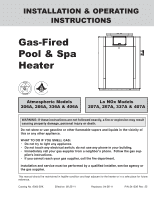
INSTALLATION & OPERATING
INSTRUCTIONS
Gas-Fired
Pool & Spa
Heater
Catalog No. 6000.59X
Effective: 08-25-11
Replaces: 04-26-11
P/N 241236 Rev. 25
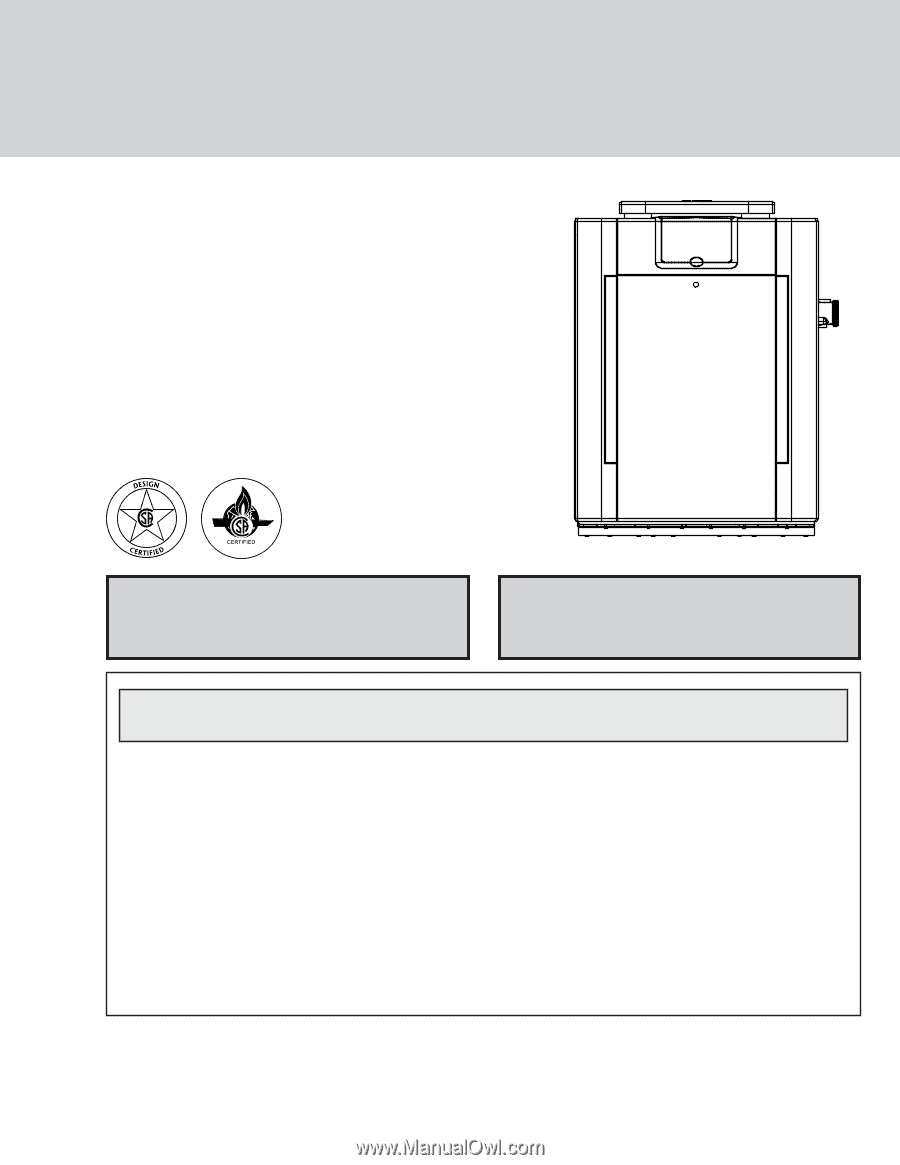
WARNING: If these instructions are not followed exactly, a fire or explosion may result
causing property damage, personal injury or death.
WHAT TO DO IF YOU SMELL GAS:
• Do not try to light any appliance.
• Do not touch any electrical switch; do not use any phone in your building.
• Immediately call your gas supplier from a neighbor's phone. Follow the gas sup-
plier's instructions.
• If you cannot reach your gas supplier, call the fire department.
Installation and service must be performed by a qualified installer, service agency or
the gas supplier.
This manual should be maintained in legible condition and kept adjacent to the heater or in a safe place for future
reference.
Atmospheric Models
206A, 266A, 336A & 406A
Lo NOx Models
207A, 267A, 337A & 407A
Do not store or use gasoline or other flammable vapors and liquids in the vicinity of
this or any other appliance.