Rheem P-M406 Operating Instructions - Page 25
HEAT EXCHANGER REVERSAL PROCEDURE - STANDARD MODELS, AFT Models, Millivolt Models, Do not over
 |
View all Rheem P-M406 manuals
Add to My Manuals
Save this manual to your list of manuals |
Page 25 highlights
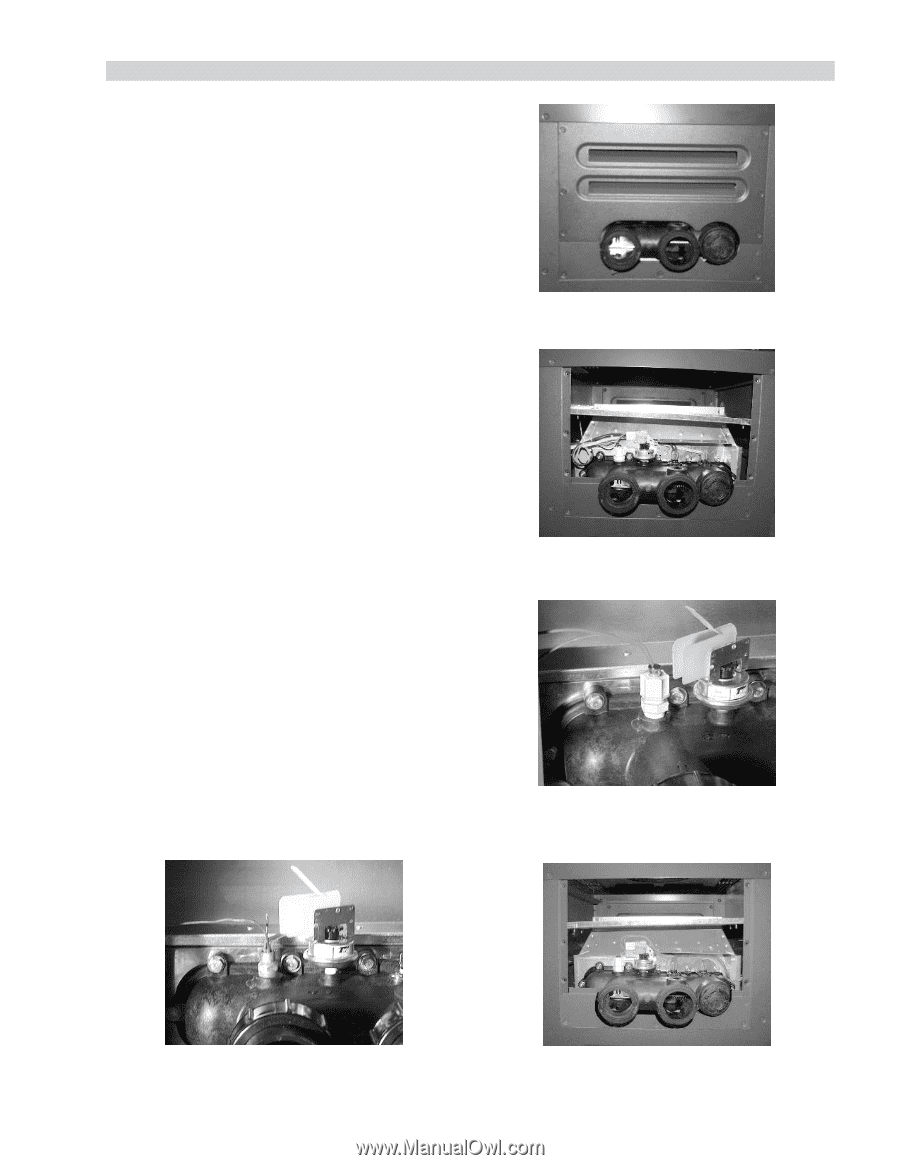
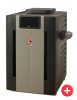
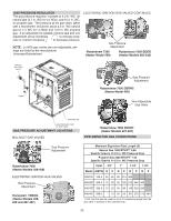
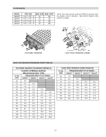
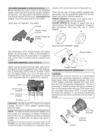
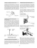
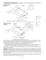
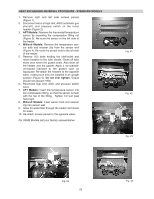
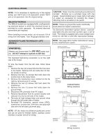
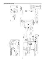
HEAT EXCHANGER REVERSAL PROCEDURE - STANDARD MODELS 1. Remove right and left side access panels (Figure 1). 2. Disconnect wires at high limit, AGS (automatic gas shut-off), and pressure switch on the in/out header (Figure 2). 3. AFT Models: Remove the thermostat temperature sensor by loosening the compression fitting nut (Figure 3). Re-route the sensor to the left side of the heater. 4. Millivolt Models: Remove the temperature sensor bulb and retainer clip from the sensor well (Figure 4). Re-route the sensor bulb to the left side of the heater. 5. Remove (12) bolts holding the inlet/outlet and return headers to the tube sheets. Clean off tube sheet area where the gasket seats. Also clean off the header and the gasket. Apply a non-petroleum-based lubricant to the gasket such as AquaLube. Re-attach the headers to the opposite sides, making sure they are installed in an upright position (Figure 5). Do not over tighten. Torque should not exceed 7 ft/lb. 6. Reconnect high limit, AGS, and pressure switch wires. 7. AFT Models: Insert the temperature sensor into the compression fitting, so that the sensor is flush with the top of the fitting. Tighten 1/2 turn past hand-tight. 8. Millivolt Models: Insert sensor bulb and retainer clip into sensor well. 9. Allow for water flow through the heater and check for leaks. 10. Re-attach access panels to the opposite sides. For ASME Models call your factory representative. Fig. #1 Fig. #2 Fig. #3 Fig. #4 25 Fig. #5
-
 1
1 -
2
-
3
-
4
-
5
-
6
-
7
-
8
-
9
-
10
-
11
-
12
-
13
-
14
-
15
-
16
-
17
-
18
-
19
-
 20
20 -
 21
21 -
 22
22 -
 23
23 -
 24
24 -
 25
25 -
 26
26 -
 27
27 -
 28
28 -
 29
29 -
 30
30 -
31
-
32
-
33
-
34
-
35
-
36
-
37
-
38
-
39
-
40
-
41
-
42
-
43
-
44
-
45
-
46
-
47
-
48
-
49
-
50
-
51
-
52
-
53
-
54
-
55
-
56
 |
 |