Rheem P-M406 Operating Instructions - Page 18
For more information consult the D-2 Power Vent manual, Catalog No. 6000.57.1.
 |
View all Rheem P-M406 manuals
Add to My Manuals
Save this manual to your list of manuals |
Page 18 highlights
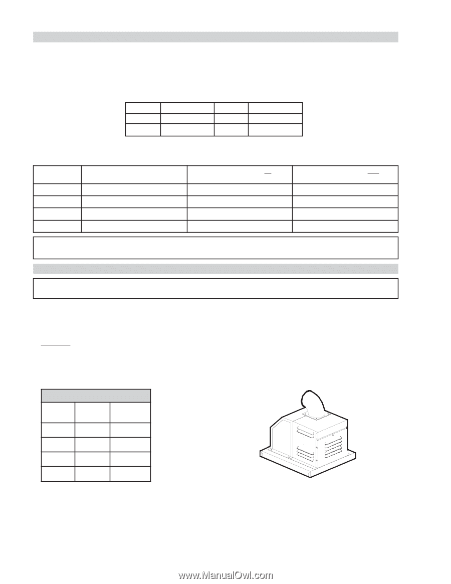
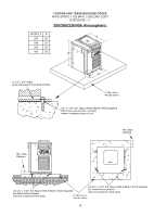
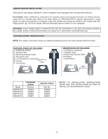
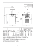
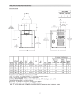
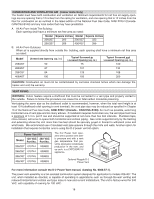
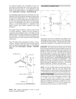
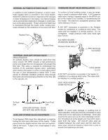
COMBUSTION AND VENTILATION AIR (Indoor Units Only) The heater must have both combustion and ventilation air. Minimum requirements for net free air supply openings are one opening that is 12 inches from the ceiling for ventilation, and one opening that is 12 inches from the floor for combustion air as outlined in the latest edition of the National Fuel Gas Code, ANSI Z223.1(CanadaCAN/CSA-B149) and any local codes that may have jurisdiction. A. All Air From Inside The Building: Each opening shall have a minimum net free area as noted: Model Square Inches Model Square Inches 206/207 200 336/337 333 266/267 266 406/407 399 B. All Air From Outdoors: When air is supplied directly from outside the building, each opening shall have a minimum net free area as noted: Model 206/207 Unrestricted Opening (sq. in.) 50 Typical Screened or Louvered Opening (sq. in.) 75 Typical Screened and Louvered Opening (sq. in.) 100 266/267 67 101 134 336/337 84 126 168 406/407 100 150 200 CAUTION: Combustion air must not be contaminated by corrosive chemical fumes which can damage the heater and void the warranty. VENT PIPING WARNING: Indoor heaters require a drafthood that must be connected to a vent pipe and properly vented to the outside. Failure to follow this procedure can cause fire or fatal carbon monoxide poisoning. Vent piping the same size as the drafthood outlet is recommended, however, when the total vent height is at least 10 ft (drafthood relief opening to vent terminal), the vent pipe size may be reduced as specified in Chapter 10 of the National Fuel Gas Code, ANSI Z223.1 (Canada - CAN/CSA-B149). As much as possible, avoid long horizontal runs of vent pipe and too many elbows. If installation requires horizontal runs, the vent pipe must have a minimum of 1/4 in. per ft rise and should be supported at not more than five foot intervals. Plumbers tape, criss-crossed, will serve to space both horizontal and vertical piping. Gas vents supported only by the flashing and extending above the roof more than five feet should be securely guyed or braced to withstand snow and wind loads. We recommend use of insulated vent pipe spacers through the roofs and walls. Another option for installation that requires horizontal runs is using the D-2 power vent kit option. Power Vent Kit Model 120 VAC Part No. 240 VAC Part No. 206/207 010744 009832 266/267 010744 009832 336/337 010745 009833 406/407 010745 009833 The D-2 Power Vent operates with a positve vent static pressure and with a vent gas temperature that prevents excessive condensate production in the vent, and as such, is a CATEGORY III appliance. Optional Raypak D-2 Power Vent For more information consult the D-2 Power Vent manual, (Catalog No. 6000.57.1). The power vent assembly is a fan-assisted combustion system designed for application to models 206-407. The unit, when installed as directed, is capable of operating in applications such as through-the-wall venting and reduced horizontal and vertical vent pipe sizes in new and current installations. The unit is factory-wired for 240 VAC, with capability of rewiring for 120 VAC. 18
-
 1
1 -
2
-
3
-
4
-
5
-
6
-
7
-
8
-
9
-
10
-
11
-
12
-
 13
13 -
 14
14 -
 15
15 -
 16
16 -
 17
17 -
 18
18 -
 19
19 -
 20
20 -
 21
21 -
 22
22 -
 23
23 -
24
-
25
-
26
-
27
-
28
-
29
-
30
-
31
-
32
-
33
-
34
-
35
-
36
-
37
-
38
-
39
-
40
-
41
-
42
-
43
-
44
-
45
-
46
-
47
-
48
-
49
-
50
-
51
-
52
-
53
-
54
-
55
-
56
 |
 |