Ryobi A25RT02 English Manual
Ryobi A25RT02 Manual
 |
View all Ryobi A25RT02 manuals
Add to My Manuals
Save this manual to your list of manuals |
Ryobi A25RT02 manual content summary:
- Ryobi A25RT02 | English Manual - Page 1
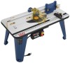
OPERATOR'S MANUAL ROUTER TABLE A25RT02 3 2 1 0 1 Inch inch 3 2 1 0 1 Inch Your router table has been engineered and manufactured to our high standard for dependability, ease of operation, and operator safety. When properly cared for, it will give you years of rugged, trouble-free performance. - Ryobi A25RT02 | English Manual - Page 2
in workmanship or materials in your RYOBI® power tool for a period of two years from the date of purchase. With the exception of batteries, power tool accessories are warranted for ninety (90) days. Batteries are warranted for two years. HOW TO GET SERVICE: Just return the power tool, properly - Ryobi A25RT02 | English Manual - Page 3
and understand all instructions. Failure to follow all instructions listed below, may result in electric shock, fire and/or serious personal injury. READ ALL INSTRUCTIONS KNOW YOUR POWER TOOL. Carefully read the router table operator's manual and the manual for the particular router you are using - Ryobi A25RT02 | English Manual - Page 4
not listed may cause the risk of personal injury. Instructions for safe use of accessories are included with the accessory. SPECIFIC SAFETY RULES FOR YOUR OWN SAFETY, read this router table operator's manual and the router manual before operating the router or using the router table. ALWAYS - Ryobi A25RT02 | English Manual - Page 5
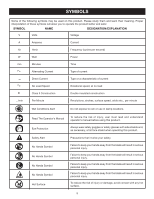
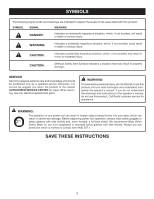
Safety Alert No Hands Symbol No Hands Symbol No Hands Symbol No Hands Symbol Hot Surface To reduce the risk of injury, user must read and understand operator's manual before using this product. Always wear safety goggles or safety glasses with side shields and, as necessary, a full face shield when - Ryobi A25RT02 | English Manual - Page 6
parts. WARNING: To avoid serious personal injury, do not attempt to use this product until you read thoroughly and understand completely the operator's manual. If you do not understand the warnings and instructions in the operator's manual, do not use this product. Call Ryobi customer service - Ryobi A25RT02 | English Manual - Page 7
listed by Underwriter's Laboratories (UL) should be used. **Ampere rating (on product data plate support one power product may not be able to support two or three products. GROUNDING INSTRUCTIONS service personnel if the grounding instructions overheat. If the router table does not operate when plugged - Ryobi A25RT02 | English Manual - Page 8
ASSEMBLY The sacrifical MDF fence assembly provides an adjustable surface to support and guide the work. Molded into the fence assembly is the vacuum port. INSERT PLATE The insert plate can be used in combination with a variety of routers. It also has pre-drilled countersunk holes that can be used - Ryobi A25RT02 | English Manual - Page 9
the router table switch box from overload. STARTING PIN When you are unable to use the fence for a guide because the workpiece is odd-shaped or too small, use the starting pin for a guide and/or pivot point. Only use piloted cutters when using the starting pin. THROAT PLATES Five throat plates are - Ryobi A25RT02 | English Manual - Page 10
4. Table Top 5. Switch Box Nut (3) 6. Switch Box Screw (3) 7. Switch Box 8. Carriage Bolt Washer (2) 9. Carriage Bolt (2) 10. Hex Key (1) 11. Under Table Guard (2) 18 DIFREEECDTION 23 19 22 3 20 3 2 1 0 1 Inch 17 21 16 15 14 13 12 11 Fig. 4 12. Throat Plates (5) 13. Router Insert Plate Screws - Ryobi A25RT02 | English Manual - Page 11
ASSEMBLING THE ROUTER TABLE Assembling the router table involves attaching the switch box, the under table guards, the legs, the router/insert plate assembly, the fence assembly, featherboard, throat plate, starting pin, and installing the miter gauge to the router table. ATTACHING THE SWITCH BOX - Ryobi A25RT02 | English Manual - Page 12
RY: Ryobi R163K ML: Milwaukee 5615-20, 5616-20 PC1: Porter-Cable 890 Series PC2: Porter-Cable 8529 ATTACHING THE ROUTER TO THE TABLE For ease of use, assemble the router to the insert plate with the insert plate removed first, then install the insert plate/ router assembly into the router table - Ryobi A25RT02 | English Manual - Page 13
MODEL BASE TYPE FASTENER SIZE INSERT PLATE Ryobi RE180PL/PL1 Plunge 5/16-18 x 3/4 in. B1, B3 2 Skil 1810 Fixed 10-32 x 5/8 in. A2, A4, A6 3 Skil 1825 Fixed/Plunge 10-32 x 5/8 in. A2, A4, A6 3 All identified trademarks and trade names are the property of their respective owners - Ryobi A25RT02 | English Manual - Page 14
screws depending on how the insert plate needs to beInch 1 adjusted in order to make the insert plate level. Tighten insert plate screws with a screwdriver. ATTACHING THE FENCE ASSEMBLY See Figure 13. Unplug the router table and/or the router. Place the router table right side up with the - Ryobi A25RT02 | English Manual - Page 15
until it snaps into place. 3 2 To remove, push throat plate out from1 0 1 the bottom of the Inch insert plate. ATTACHING THE FEATHERBOARD See Figure 15. Unplug the router table and/or the router. Insert the featherboard bolts through the slots in the fence assembly. Slide - Ryobi A25RT02 | English Manual - Page 16
workbench, counter top. Using a clamp, insert the top front of clamp through the opening in the router table leg. Tighten clamp securely. MOUNTING THE ROUTER TABLE TO A WORK BENCH See Figure 20. Unplug the router table and/or the router. Place the router table right side up on a sturdy work - Ryobi A25RT02 | English Manual - Page 17
operator's manual for the router and router table. Plug the router table power cord into a power source. Always control the power to the router with the router table switch whenever the router is mounted on the table. Always plug the router into either of the router table switched outlets - Ryobi A25RT02 | English Manual - Page 18
router table and/or the router. Remove the router/insert plate assembly. (See Installing Router/Insert Plate 0 1 Inch Consult the router operator's manual for proper cutter removal/installation procedure you to support and guide the workpiece. Unplug the router table and/or the router. - Ryobi A25RT02 | English Manual - Page 19
MAINTENANCE WARNING: When servicing, use only identical replacement parts. Use of any other parts may create a hazard or also wear a dust mask. GENERAL MAINTENANCE Avoid using solvents when cleaning plastic parts. Most plastics are susceptible to damage from various types of commercial solvents and - Ryobi A25RT02 | English Manual - Page 20
OPERATOR'S MANUAL ROUTER TABLE A25RT02 WARNING: Some PARTS AND SERVICE Prior to requesting service or purchasing replacement parts, please obtain your model and serial number from the product data plate. • MODEL NUMBER A25RT02 • SERIAL NUMBER • HOW TO OBTAIN REPLACEMENT PARTS: Replacement parts
-
 1
1 -
 2
2 -
 3
3 -
 4
4 -
 5
5 -
 6
6 -
 7
7 -
8
-
9
-
10
-
11
-
12
-
13
-
14
-
15
-
16
-
17
-
18
-
19
-
20
 |
 |

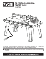
OPERATOR’S MANUAL
ROUTER TABLE
A25RT02
Inch
1
0
1
2
3
Inch
1
0
1
2
3
inch
SAVE THIS MANUAL FOR FUTURE REFERENCE
Your
router table
has been engineered and manufactured to our high standard for dependability, ease of operation, and
operator safety. When properly cared for, it will give you years of rugged, trouble-free performance.
WARNING:
To reduce the risk of injury, the user must read and understand the operator’s manual before using
this product.
Thank you for your purchase.