Ryobi A25RT02 English Manual - Page 14
Making Insert Plate Level, Attaching The Fence Assembly, Inserting And Removing Throat, Plates - table
 |
View all Ryobi A25RT02 manuals
Add to My Manuals
Save this manual to your list of manuals |
Page 14 highlights
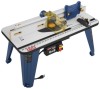
ASSEMBLY MAKING INSERT PLATE LEVEL See Figure 12. Unplug the router table and/or the router. Check to see if the insert plate mounted assembly is level with a straight edge or level. INSERT PLATE STRAIGHT EDGE Loosen insert plate screws. 3 Using the supplied hex key, tighten or loosen the adjust- 2 1 0 ing screws depending on how the insert plate needs to beInch 1 adjusted in order to make the insert plate level. Tighten insert plate screws with a screwdriver. ATTACHING THE FENCE ASSEMBLY See Figure 13. Unplug the router table and/or the router. Place the router table right side up with the back edge closest to you. Slide the carriage bolt washers onto the carriage bolts. Slide carriage bolts through the slot in the router table and through the slots in the fence assembly. Slide the fence lock knob washer over the carriage bolts. FENCE LOCK KNOB WASHER Install the fence lock knobs over the carriage bolts. Tighten the fence lock knobs. HEX KEY ADJUSTING SCREWS DIFREEECDTION 3 2 1 0 1 Inch Fig. 12 FENCE FENCE LOCK KNOBS ASSEMBLY 1 Inch 0 3 2 1 0 WARNING: Make sure throat plates snap securely into place. Do not use if snaps are damaged or throat plates do not snap in securely. Failure to do so could result in serious personal injury. INSERTING AND REMOVING THROAT PLATES See Figure 14. The throat plate provides a stable surface around the cutter and prevents objects from falling through the throat plate and damaging the spindle. The proper size throat plate depends on the size and shape of the cutter. When inserted, the throat plate opening should be within approximately 1/4 in. of the outermost edge of the cutter. SLOT CARRIAGE BOLT WASHER CARRIAGE BOLTS THROAT PLATE Fig. 13 TAB 3 2 1 0 1 Inch NOTCH 1 Inch 3 2 1 0 Fig. 14 DIFREEECDTION 14
-
 1
1 -
2
-
3
-
4
-
5
-
6
-
7
-
8
-
 9
9 -
 10
10 -
 11
11 -
 12
12 -
 13
13 -
 14
14 -
 15
15 -
 16
16 -
 17
17 -
 18
18 -
 19
19 -
20
 |
 |
