Ryobi TS1142L User Manual - Page 11
Features, Tools Needed
 |
View all Ryobi TS1142L manuals
Add to My Manuals
Save this manual to your list of manuals |
Page 11 highlights
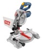
FEATURES SWITCH TRIGGER The saw will not start until you depress the switch lock with your thumb then squeeze the switch trigger. To prevent unauthorized use of the compound miter saw, disconnect it from the power supply and lock the switch in the off position. To lock the switch, install a padlock (not included) through the hole in the switch trigger. A lock with a long shackle of 5/16 in. diameter may be used. When the lock is installed and locked, the switch is inoperable. Store the padlock key in another location. Switch lock Switch trigger Padlock TOOLS NEEDED The following tool (not included) is needed for making adjustments or installing the blade: Fig. 4 Square 11 Fig. 5
-
 1
1 -
2
-
3
-
4
-
5
-
 6
6 -
 7
7 -
 8
8 -
 9
9 -
 10
10 -
 11
11 -
 12
12 -
 13
13 -
 14
14 -
 15
15 -
 16
16 -
17
-
18
-
19
-
20
-
21
-
22
-
23
-
24
-
25
-
26
-
27
-
28
-
29
-
30
-
31
-
32
-
33
-
34
-
35
-
36
-
37
-
38
-
39
-
40
-
41
-
42
-
43
-
44
-
45
-
46
-
47
-
48
-
49
-
50
-
51
-
52
-
53
-
54
-
55
-
56
-
57
-
58
-
59
-
60
-
61
-
62
-
63
-
64
-
65
-
66
-
67
-
68
-
69
-
70
-
71
-
72
-
73
-
74
-
75
-
76
-
77
-
78
-
79
-
80
-
81
-
82
-
83
-
84
-
85
-
86
-
87
-
88
-
89
-
90
-
91
-
92
 |
 |

11
FEATURES
SWITCH TRIGGER
The saw will not start until you depress the switch lock with
your thumb then squeeze the switch trigger. To prevent
unauthorized use of the compound miter saw, disconnect it
from the power supply and lock the switch in the off position.
To lock the switch, install a padlock (not included) through
the hole in the switch trigger. A lock with a long shackle of
5/16 in. diameter may be used. When the lock is installed
and locked, the switch is inoperable. Store the padlock key
in another location.
The following tool (not included) is needed for making adjustments or installing the blade:
TOOLS NEEDED
Fig. 5
SQUARE
Fig. 4
PADLOCK
SWITCH
TRIGGER
SWITCH
LOCK