Seagate 15K.3 ST373453FC Model Product Manual PDF - Page 42
Cheetah 15K.3 FC Product Manual, Rev. D, Mechanical specifications
 |
UPC - 000004165019
View all Seagate 15K.3 manuals
Add to My Manuals
Save this manual to your list of manuals |
Page 42 highlights
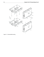
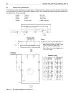
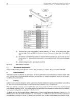
32 Cheetah 15K.3 FC Product Manual, Rev. D 6.5 Mechanical specifications The following nominal dimensions are exclusive of the decorative front panel accessory. However, dimensions of the front panel are shown in figure below. Refer to Figure 13 for detailed mounting configuration dimensions. See Section 8.5, "Drive mounting." Height: Width: Depth: Weight: 1.000 in 4.000 in 5.75 in 1.85 pounds 25.4 mm 101.6 mm 146.05 mm 0.842 kilograms H // T -Z- S [1] A -Z- M U -XP B L R N -Z- C -X- F [1] E D -X- Figure 13. Mounting configuration dimensions J K -Z- Notes: [1] Mounting holes are 6-32 UNC 2B, three on each side and four on the bottom. Max screw penetration into side of drive is 0.15 in. (3.81 mm). Max screw tightening torque is 6.0 in-lb (3.32 nm) with minimum full thread engagement of 0.12 in. (3.05 mm). Dimension Table Inches Millimeters A 1.028 max 26.10 max B 5.787 max 147.00 max C 4.000 ± .010 101.60 ± .25 D 3.750 ± .010 95.25 ± .25 E 0.125 ± .010 3.18 ± .25 F 1.750 ± .010 44.45 ± .25 H 1.122 ± .020 28.50 ± .50 J 4.000 ± .010 101.60 ± .25 K 0.250 ± .010 6.35 ± .25 L 1.638 ± .010 41.60 ± .25 M 0.181 ± .020 4.60 ± .50 N .015 max .038 max P 1.625 ± .020 41.28 ± .50 R 1.469 ± .020 37.31 ± .50 S 0.276 ± .040 7.00 ± 1.02 T .015 max 0.38 max U .015 max 0.38 max
-
 1
1 -
2
-
3
-
4
-
5
-
6
-
7
-
8
-
9
-
10
-
11
-
12
-
13
-
14
-
15
-
16
-
17
-
18
-
19
-
20
-
21
-
22
-
23
-
24
-
25
-
26
-
27
-
28
-
29
-
30
-
31
-
32
-
33
-
34
-
35
-
36
-
 37
37 -
 38
38 -
 39
39 -
 40
40 -
 41
41 -
 42
42 -
 43
43 -
 44
44 -
 45
45 -
 46
46 -
 47
47 -
48
-
49
-
50
-
51
-
52
-
53
-
54
-
55
-
56
-
57
-
58
-
59
-
60
-
61
-
62
-
63
-
64
-
65
-
66
-
67
-
68
-
69
-
70
-
71
-
72
-
73
-
74
-
75
-
76
-
77
-
78
-
79
-
80
-
81
-
82
-
83
-
84
-
85
-
86
 |
 |
