Seagate 15K.3 ST373453FC Model Product Manual PDF - Page 46
Cheetah 15K.3 FC Product Manual, Rev. D, J6 connector requirements, Drive orientation, Cooling
 |
UPC - 000004165019
View all Seagate 15K.3 manuals
Add to My Manuals
Save this manual to your list of manuals |
Page 46 highlights
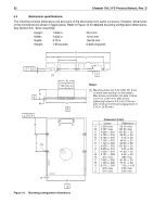
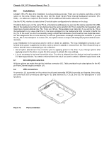
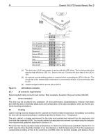
36 Cheetah 15K.3 FC Product Manual, Rev. D Drive Front Pin 1 J6 Reserved Port A Bypass LED [1] Port B Bypass LED [1] Fault LED [1] Reserved Active LED [2] Reserved +5V Active LED [1] Ground [3] [1] The drive has a 2.2K ohm resistor in series with this LED driver. Tie the minus side of an external high-efficiency LED (i.e., 2ma) to this pin. Connect the plus side of the LED to +5V. [2] An external current-limiting resistor is required when connecting an LED to this pin. The minus side of the resistor/LED combination is connected to this pin. Connect the plus side to +5V. [3] Jumper storage location (across pins 2 and 4). Figure 15. LED indicator connector 8.2.1 J6 connector requirements Recommended mating connector part number: Berg receptacle, 6-position, Berg part number 690-006. 8.3 Drive orientation The drive may be mounted in any orientation. All drive performance characterizations, however, have been done with the drive in horizontal (discs level) and vertical (drive on its side) orientations, which are the two preferred mounting orientations. 8.4 Cooling Cabinet cooling must be designed by the customer so that the ambient temperature immediately surrounding the drive will not exceed temperature conditions specified in Section 6.4.1, "Temperature." The rack, cabinet, or drawer environment for the drive must provide heat removal from the electronics and head and disc assembly (HDA). You should confirm that adequate heat removal is provided using the temperature measurement guidelines described in Section 6.4.1. Forced air flow may be required to keep temperatures at or below the temperatures specified in Section 6.4.1 in which case the drive should be oriented, or air flow directed, so that the least amount of air flow resistance is created while providing air flow to the electronics and HDA. Also, the shortest possible path between the air
-
 1
1 -
2
-
3
-
4
-
5
-
6
-
7
-
8
-
9
-
10
-
11
-
12
-
13
-
14
-
15
-
16
-
17
-
18
-
19
-
20
-
21
-
22
-
23
-
24
-
25
-
26
-
27
-
28
-
29
-
30
-
31
-
32
-
33
-
34
-
35
-
36
-
37
-
38
-
39
-
40
-
 41
41 -
 42
42 -
 43
43 -
 44
44 -
 45
45 -
 46
46 -
 47
47 -
 48
48 -
 49
49 -
 50
50 -
 51
51 -
52
-
53
-
54
-
55
-
56
-
57
-
58
-
59
-
60
-
61
-
62
-
63
-
64
-
65
-
66
-
67
-
68
-
69
-
70
-
71
-
72
-
73
-
74
-
75
-
76
-
77
-
78
-
79
-
80
-
81
-
82
-
83
-
84
-
85
-
86
 |
 |
