Seagate ST800FM0012 Pulsar.2 SAS Product Manual - Page 37
Seagate ST800FM0012 Manual
 |
View all Seagate ST800FM0012 manuals
Add to My Manuals
Save this manual to your list of manuals |
Page 37 highlights
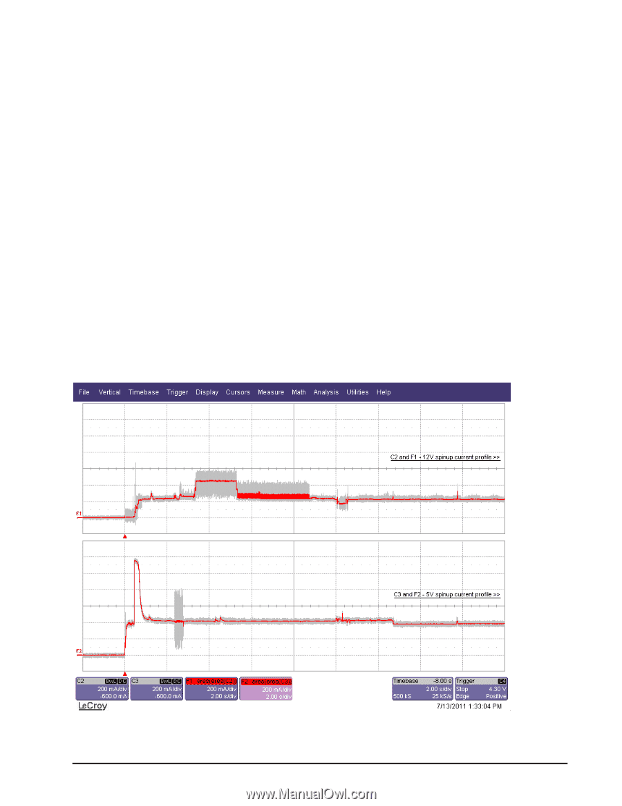
General DC power requirement notes. 1. Minimum current loading for each supply voltage is not less than 1.7% of the maximum operating current shown. 2. The +5V and +12V supplies should employ separate ground returns. 3. Where power is provided to multiple drives from a common supply, careful consideration for individual drive power requirements should be noted. Where multiple units are powered on simultaneously, the peak starting current must be available to each device. 4. Parameters, other than start, are measured after a 10-minute warm up. 7.3.1 Conducted noise immunity Noise is specified as a periodic and random distribution of frequencies covering a defined frequency. Maximum allowed noise values given below are peak-to-peak measurements and apply at the drive power connector. +5v +12v = = 250 mV pp from 100 Hz to 20 MHz. 450 mV pp from 100 Hz to 100 KHz. 250 mV pp from 100 KHz to 20 MHz. 150 mV pp from 20 MHz to 80 MHz. 7.3.2 Power sequencing The drive does not require power sequencing. The drive protects against inadvertent writing during power-up and down. 7.3.3 Current profiles The +12V and +5V current profiles for the Pulsar.2 drives are shown below. Figure 1. Current profiles for 800GB models Pulsar.2 SAS Product Manual, Rev. B 29
-
 1
1 -
2
-
3
-
4
-
5
-
6
-
7
-
8
-
9
-
10
-
11
-
12
-
13
-
14
-
15
-
16
-
17
-
18
-
19
-
20
-
21
-
22
-
23
-
24
-
25
-
26
-
27
-
28
-
29
-
30
-
31
-
 32
32 -
 33
33 -
 34
34 -
 35
35 -
 36
36 -
 37
37 -
 38
38 -
 39
39 -
 40
40 -
 41
41 -
 42
42 -
43
-
44
-
45
-
46
-
47
-
48
-
49
-
50
-
51
-
52
-
53
-
54
-
55
-
56
-
57
-
58
-
59
-
60
-
61
-
62
-
63
-
64
-
65
-
66
-
67
-
68
-
69
-
70
-
71
-
72
-
73
-
74
-
75
-
76
-
77
-
78
-
79
-
80
-
81
-
82
 |
 |