Seagate ST94019A Momentus 4200 Product Manual - Page 27
Configuring and mounting the drive
 |
View all Seagate ST94019A manuals
Add to My Manuals
Save this manual to your list of manuals |
Page 27 highlights
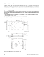
3.0 Configuring and mounting the drive This section contains the specifications and instructions for configuring and mounting the drive. 3.1 Handling and static discharge precautions After unpacking, and before installation, the drive may be exposed to potential handling and electrostatic discharge (ESD) hazards. Observe the following standard handling and static-discharge precautions: Caution: • Keep the drive in the electrostatic discharge (ESD) bag until you are ready for installation to limit the drive's exposure to ESD. • Before handling the drive, put on a grounded wrist strap, or ground yourself frequently by touching the metal chassis of a computer that is plugged into a grounded outlet. Wear a grounded wrist strap throughout the entire installation procedure. • Handle the drive only by its edges or frame. • The drive is fragile-handle it with care. Do not press down on the drive top cover. • Always rest the drive on a padded, antistatic surface until you mount it in the computer. • Do not touch the connector pins or the printed circuit board. • Do not remove the factory-installed labels from the drive or cover them with additional labels. Removal voids the warranty. Some factory-installed labels contain information needed to service the drive. Other labels are used to seal out dirt and contamination. 3.2 Jumper settings 3.2.1 Master/slave configuration Use the options jumper block shown in Figure 3 to configure the drive for operation. This jumper block is the 4pin header adjacent to pins 1 and 2 of the I/O signal pins. For additional information about using the Cable select option, see Section 3.2.2. The "Master or single drive" option is the factory default setting. Drive is master (or single drive) Drive is slave Cable select Figure 3. Jumper settings Momentus 42 Product Manual, Rev. A 17
-
 1
1 -
2
-
3
-
4
-
5
-
6
-
7
-
8
-
9
-
10
-
11
-
12
-
13
-
14
-
15
-
16
-
17
-
18
-
19
-
20
-
21
-
 22
22 -
 23
23 -
 24
24 -
 25
25 -
 26
26 -
 27
27 -
 28
28 -
 29
29 -
 30
30 -
 31
31 -
 32
32 -
33
-
34
-
35
-
36
-
37
-
38
-
39
-
40
-
41
-
42
-
43
-
44
-
45
-
46
-
47
-
48
 |
 |
