Seagate ST94019A Momentus 4200 Product Manual - Page 29
ATA interface
 |
View all Seagate ST94019A manuals
Add to My Manuals
Save this manual to your list of manuals |
Page 29 highlights
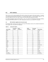
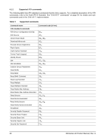
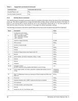
4.0 ATA interface These drives use the industry-standard ATA task file interface that supports 16-bit data transfers. It supports ATA programmed input/output (PIO) modes 0-4; multiword DMA modes 0-2, and Ultra DMA modes 0-5. The drive also supports the use of the IORDY signal to provide reliable high-speed data transfers. For detailed information about the ATA interface, refer to the draft of AT Attachment with Packet Interface Extension (ATA/ATAPI-6), NCITS T13 1410D, subsequently referred to as the Draft ATA-6 Standard. 4.1 ATA interface signals and connector pins The following table summarizes the signals on the 44-pin ATA interface connector. For a detailed description of these signals, refer to the Draft ATA-6 Standard. Table 6: Connector signals Signal Name RESETDD7 DD6 DD5 DD4 DD3 DD2 DD1 DD0 Ground DMARQ DIOWDIORIORDY DMACKINTRQ DA1 DA0 CS1FXDASP+5 V (Logic) Ground (Return) Connector Contact 1 3 5 7 9 11 13 15 17 19 21 23 25 27 29 31 33 35 37 39 41 43 Cable Conductor 1 3 5 7 9 11 13 15 17 19 21 23 25 27 29 31 33 35 37 39 41 43 Cable Conductor 2 4 6 8 10 12 14 16 18 20 22 24 26 28 30 32 34 36 38 40 42 44 Connector Contact 2 4 6 8 10 12 14 16 18 20 22 24 26 28 30 32 34 36 38 40 42 44 Signal Name Ground DD8 DD9 DD10 DD11 DD12 DD13 DD14 DD15 (keypin) Ground Ground Ground PSYNC:CSEL Ground IOCS16PDIAGDA2 CS3FXGround +5V (Motor) No connection Momentus 42 Product Manual, Rev. A 19
-
 1
1 -
2
-
3
-
4
-
5
-
6
-
7
-
8
-
9
-
10
-
11
-
12
-
13
-
14
-
15
-
16
-
17
-
18
-
19
-
20
-
21
-
22
-
23
-
 24
24 -
 25
25 -
 26
26 -
 27
27 -
 28
28 -
 29
29 -
 30
30 -
 31
31 -
 32
32 -
 33
33 -
 34
34 -
35
-
36
-
37
-
38
-
39
-
40
-
41
-
42
-
43
-
44
-
45
-
46
-
47
-
48
 |
 |
