Sharp MS722 Service Manual
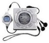
Sharp MS722 - MiniDisc Recorder - Metallic Manual
 |
UPC - 074000410077
View all Sharp MS722 manuals
Add to My Manuals
Save this manual to your list of manuals |
Sharp MS722 manual content summary:
- Sharp MS722 | Service Manual - Page 1
parts identical to those specified be used. CONTENTS Page SAFETY PRECAUTION FOR SERVICE MANUAL (MD-MS722W/MS721W ONLY 2 SPECIFICATIONS ...3 NAMES OF PARTS ...4 OPERATION MANUAL ...6 QUICK GUIDE (MD-MS722 ONLY) ...9 DISASSEMBLY ...11 INSTALLING THE TOP CABINET ...11 REMOVING AND REINSTALLING THE - Sharp MS722 | Service Manual - Page 2
MD-MS722/C/W/MS721W SAFETY PRECAUTION FORSERVICE MANUAL (MD-MS722W/MS721W ONLY) Precaution to be taken when replacing and servicing the Laser Pickup. CAUTION The AEL (Accessible Emission Level) of Laser Power portable minidisc recorder only in accordance with the instructions given in this manual - Sharp MS722 | Service Manual - Page 3
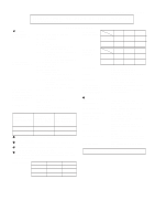
THE OPERATION MANUAL. SPECIFICATIONS General Power source: (MS722/MS722C) Power source: (MS722W/MS721W) Power consumption: (MS722/MS722C) Power consumption: (MS722W/MS721W) Output power: Charging time: Battery life: DC 3.6 V (rechargeable lithium-ion battery x 1) DC 5 V (AC adaptor) AC 120V, 60 - Sharp MS722 | Service Manual - Page 4
MD-MS722/MS722C/MS722W NAME OF PARTS Remote control unit 1. Synchro Recording Indicator 2. Character/Time Information Indicator 3. Record Indicator 4. Repeat Indicator: 5. Random Indicator 6. Disc Mode Indicator 10 7. Total Track Number Display 8. Track Number Indicator 9. Battery - Sharp MS722 | Service Manual - Page 5
29. Stop/Power Off Button: /:OFF 30. Eject Lever 31. Optical/Line Input Socket 32. Microphone Input Socket 33. Hold Switch 34. Battery Case Connection Terminals 35. Earphones Socket 36. 5V DC Input Socket 37. Rechargeable Lithium-lon Battery Compartment - 5 - MD-MS722/C/W/MS721W 1 2 3 6 SYNC - Sharp MS722 | Service Manual - Page 6
Do not force open the rechargeable battery cover too wide. When the AC adaptor plug is inserted and a MiniDisc has already been inserted, playback may start automatically. In this case, press the / :OFF button twice to turn the power off. (Illustration: MD-MS722W) CONVENIENT OPERATION OF THE UNIT - Sharp MS722 | Service Manual - Page 7
MD-MS722/C/W/MS721W - 7 - TROUBLESHOOTING Moisture condensation In the following cases, into the unit, remove the AC adaptor from the AC socket immediately and contact an authorised SHARP service centre. MINIDISC SYSTEM LIMITATIONS MiniDiscs are recorded using a different system than - Sharp MS722 | Service Manual - Page 8
MD-MS722/C/W/MS721W - 8 - ERROR MESSAGES Error messages BATT EMPTY (Lo BATT) Meaning The battery run down. BLANK DISC (BLANK) Can't COPY (Not REC) Can't EDIT Nothing is recorded another recordable disc. Return the HOLD switch to its original position. Turn off the power and remove the MiniDisc. - Sharp MS722 | Service Manual - Page 9
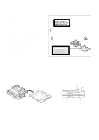
PORTABLE MINIDISC RECORDER Quick Guide/Guía rápida MD-MS722 1 Check the supplied accessories / Compruebe los accesorios suministrados Remote Control Unit x 1 Controlador remoto x 1 Headphones x 1 Auriculares x 1 AC Adaptor x 1 Adaptador de CA x 1 Rechargeable Lithium-Ion Battery x 1 Batería - Sharp MS722 | Service Manual - Page 10
MD-MS722/C/W/MS721W - 10 - 4 Recording / Grabación Recording from CDs or MDs (Synchro recording) Grabación de discos compactos o MiniDisc, with the label side facing up. Cargue un minidisco en el sentido indicado por la flecha del minidisco, con el lado de la etiqueta hacia arriba. The power - Sharp MS722 | Service Manual - Page 11
x1 ø1.4x2mm (A1)x1 1. Remove the batteries from the machine, and take out the mini rear part, and remove in the arrow direction. (Illustration: MD-MS722) 11-3 Pull Pull Pull Pull Pull Pull (C3)x3 11-2 Mechanism Unit ø1.4x2.5mm Cares when servicing: Be sure to use the screw with washer - Sharp MS722 | Service Manual - Page 12
MD-MS722/C/W/MS721W REMOVING AND REINSTALLING THE MAIN PARTS Remove the mechanism according sled motor. Note: Take care so that the motor gear is not damaged. (B1)x2 Remove the solder joint MD Mechanism Figure 12-1 (B3)x1 ø1.4x5.5mm Lift Motor (B2)x1 ø1.4x1.5mm How to remove the magnetic head - Sharp MS722 | Service Manual - Page 13
disc MMD-212 (TEAC Test MD) 88GMMD-110 88GMMD-212 3 Low reflection disc Recording minidisc UDSKM0001AFZZ Note: Use the low reflection disc on which music has been recorded. Entering the TEST mode 1. Setting at port (in standby state, disc-free state or power nonconnected state) (1) Set the port - Sharp MS722 | Service Manual - Page 14
MD-MS722/C/W/MS721W Operation in each TEST mode 1. AUTO1 Mode • When the out of range, and adjustment error. 3. MANUAL1 Mode • Adjustment item to be made in AUTO1 mode is performed manually. • When the VOL UP button is pressed during adjustment, the setting increases, and the new setting is output - Sharp MS722 | Service Manual - Page 15
MD-MS722/C/W/MS721W •Whenever the DISP button is pressed in the continuous playback mode, the in the TEST-REC mode or continuous record mode, the laser record power changes. (Servo gain changes also according to record power.) * After the laser record power is indicated for one second, the address - Sharp MS722 | Service Manual - Page 16
MD-MS722/C/W/MS721W into EEPROM, the value shown adove is recorded at the specified address. [2] Temperature measurement +28oC ~ +30oC + 02h + 29.0oC +31oC ~ +33oC + 03h + 31.8oC [3] Power IC VREF feed control output • After automatic adjustment the temperature code is read. If it is within - Sharp MS722 | Service Manual - Page 17
1 4 H A A H 7 9 H 4 F H 1 0 H 6 0 H F 2 H F 2 H 1 0 H 6 1 H 8 B H BASS setting Item display BS1 _ BS2 _ BS3 _ Set values 0 0 H 2 D H 4 B H MD-MS722/C/W/MS721W Sled setting Item display S L G _ S L 2 _ S L M _ S L V _ S K k _ S K t _ S K m _ W T m _ M V 1 _ M V 2 _ S R V _ ADJ. SET setting Item - Sharp MS722 | Service Manual - Page 18
MD-MS722/C/W/MS721W - 18 - Test Mode Change Chart Tset Mode Menu T E S T SKIP -autoadjustment menu : ATT autoadjustment menu : Continuous playback menu : Continuous record menu : Pre-manual adjustment menu : ATT manual adjustment menu : Preadjustment value check menu : ATT adjustment value check - Sharp MS722 | Service Manual - Page 19
ATT Auto Adjustment Pre-Manual Adjustment MD-MS722/C/W/MS721W - 19 - A U T O 2 PLAY : ATT Autoadjustment menu A T 2 : During ATT autoadjustment signal offset (FINO) tentative measurement : Measurement value : Laser On (Play Power) : RF side focus gain coarse adjustment : Gain setting : A-ATT ( - Sharp MS722 | Service Manual - Page 20
MD-MS722/C/W/MS721W - 20 - Continued from the preceding page SKIP UP R F G SKIP DOWN SKIP SKIP UP L B SKIP DOWN : Temperature code displayATT manual adjustment menu : Temperature code display $ $ : Temperature code : Laser ON (Play Power) : Pit section E-ATT (tracking) setting : ATT setting - Sharp MS722 | Service Manual - Page 21
MD-MS722/C/W/MS721W - 21 - Pre-Adjustment Value Check R S L T 1 PLAY A H SKIP UP B H SKIP DOWN SKIP UP E H SKIP DOWN SKIP UP F H SKIP DOWN SKIP UP A L SKIP DOWN SKIP UP B L - Sharp MS722 | Service Manual - Page 22
MD-MS722/C/W/MS721W - 22 - Continuous Playback • Continuous playback from current pickup position T PLAY : Continuous playback menu PLAY S Q # # # DOWN] key is pressed. * In the continuous record state and start address set state the record laser power changes in the range of "0h to Fh" when - Sharp MS722 | Service Manual - Page 23
MD-MS722/C/W/MS721W - 23 - Inner Switch Position Measurement I N N E R PLAY : INNER switch position measurement menu S Q # # # # : Continuous playback (pit section) # # # # : Address * When the [STOP] key is pressed in specific - Sharp MS722 | Service Manual - Page 24
MD-MS722/C/W/MS721W - 24 - EEPROM Setting Focus Setting E E P R O M : EEPROM setting menu PLAY T e m p SKIP DOWN : TEMP setting menu SKIP UP SKIP DOWN F o c u s : Focus setting menu SKIP UP SKIP - Sharp MS722 | Service Manual - Page 25
MD-MS722/C/W/MS721W - 25 - Spin Setting S p i n PLAY S P G SKIP UP SP i SKIP UP SP m SKIP UP SP o SKIP UP SP 1 SKIP UP SP 2 SKIP UP S P 3 SKIP UP S P 4 SKIP - Sharp MS722 | Service Manual - Page 26
MD-MS722/C/W/MS721W - 26 - Slide Setting TEMP Setting S l e d PLAY S L G SKIP UP S L 2 SKIP UP S L M SKIP UP S L V SKIP UP S K k SKIP UP S K t SKIP UP S K m SKIP UP W T m SKIP UP M V 1 SKIP UP M V 2 - Sharp MS722 | Service Manual - Page 27
MD-MS722/C/W/MS721W - 27 - Digital EQ Setting D E Q S E T PLAY HQ 1 SKIP UP H Q 2 SKIP DOWN SKIP UP H S G SKIP UP H S O SKIP DOWN SKIP DOWN SKIP UP LQ 1 SKIP DOWN SKIP - Sharp MS722 | Service Manual - Page 28
MD-MS722/C/W/MS721W - 28 - Continued from the preceding page SKIP UP D R H SKIP DOWN SKIP UP P L E SKIP UP R C E SKIP DOWN SKIP DOWN SKIP UP E L T SKIP UP S L T SKIP DOWN - Sharp MS722 | Service Manual - Page 29
MD-MS722/C/W/MS721W Figure 29 BLOCK DIAGRAM - 29 - M903 POWER DRIVE IR3M09N VCC 8 4 IC820 12 POWER DRIVE IR3M09N VCC 8 +2.35 2 SERIES 3 REGULATOR J703 REMOTE CONTORL OVER VOLTAGE, REVERSE-CONNECTION PROTECTION CIRCUIT J801 DC IN (+4~+5.5V) RECHARGEABLE BATTERY (+2.9~+4.1V) BATTERY - Sharp MS722 | Service Manual - Page 30
EFMO MD-MS722/C/WMS721W P30 P31 P32 MAIN PWB-A C112 A PLAYBACK SIGNAL 0.033 C111 0.0033 +B TP202 RECORD SIGNAL C110 0.22 C107 C109 0.012 1/16 C106 0.22 TP139 R207 680 L204 XL201 33.8688MHz TP204 CK112 C211 5P(CH) LDCNT2 LDCNT1 AGND AVCC - Sharp MS722 | Service Manual - Page 31
P30 P31 P32 MD-MS722/C/W/MS721W R102 22K TP100 +B TP139 6 R104 22K 01 2K P487 B R103 22K R207 680 TP202 TP204 L204 XL201 33.8688MHz CK207 C211 5P(CH) LDCNT2 - Sharp MS722 | Service Manual - Page 32
MD-MS722 1 CN482 FLEXIBLE PWB LCD LCD DRIVER MS722/MS722C MS722W/MS721W(S) /MS721W(BL) R765·766 10 1K 4 3 IC841 2 5 1 XC62HS02 POWER SUPPLY MICROCOMPUTER R842 1K R811 330K R812 180K R813 100K 3 J801 DC IN 1 2 3 BATTERY TERMINAL EXT.BATTERY TERMINAL HPLAY R847 HREC 330K INN PCNT1 - Sharp MS722 | Service Manual - Page 33
MD-MS722/C/W/MS721W IC101 PIN NO. VOLTAGE 1 0.7V 2 0.7V 3 0.7V 4 0.7V 5 1.29V 6 1.26V 7 0.7V 8 1.26V 9 1.26V 10 1.26V 11 1.26V 12 1.26V 13 2.52V 14 2.52V 15 0. - Sharp MS722 | Service Manual - Page 34
MD-MS722/C/WMS721W (Only Serial No. 81101800) A J801 DC IN J703 REMOTE CONTROL/ HEADPHONES R800 C804 R809 D802 B R801 1 6 R804 4 3 4 IC801 1 R803 R802 R810 D800 D801 C805 - Sharp MS722 | Service Manual - Page 35
MD-MS722/C/W/MS721W L712 P38 6 - H LCD R723 TP711 L713 TP713 L711 TP714 TP721 C851 TP771 TP463 R459 R460 IC850 12 TP810 R859 TP811 TP461 C831 TP465 7 TP462 TP464 TP812 TP456 BATTERY,- (221) EXT. BATTERY (230) P38 4 - E, G KEY SWITCH FLEXIBLE UNIT TP404 R422 TP403 XL401 R407 1 5 - Sharp MS722 | Service Manual - Page 36
MD-MS722/C/WMS721W (From Serial No. 81201801) A J801 DC IN J703 REMOTE CONTROL/ HEADPHONES R800 C804 R809 D802 B R801 1 6 R804 4 3 4 IC801 1 R803 R802 R810 D800 D801 C805 - Sharp MS722 | Service Manual - Page 37
MD-MS722/C/W/MS721W L712 P38 6 - H LCD R723 TP711 L713 TP713 L711 TP714 TP721 C853 TP771 TP463 R459 R460 IC850 12 TP810 R859 TP811 TP461 C831 TP465 7 TP462 TP464 TP812 TP456 BATTERY,- (221) EXT. BATTERY (230) P38 4 - E, G KEY SWITCH FLEXIBLE UNIT TP404 R422 TP403 XL401 R407 1 5 - Sharp MS722 | Service Manual - Page 38
PWB UNIT (8) SW901 SW902 C CN101 TO MAIN PWB P35,37 8 - H D PH901 CN601 TO MAIN PWB P33 11 - H M903 LIFT MOTOR MAGNETIC HEAD FLEXIBLE PWB (23) MD-MS722/C/W E MAGNETIC HEAD KEY FLEXIBLE PWB ASS'Y (248) (32) CN451 TO MAIN PWB P35,37 12 - D LCD (249 - Sharp MS722 | Service Manual - Page 39
MD-MS722/C/W/MS721W NOTES ON SCHEMATIC DIAGRAM • Resistor: To differentiate the units of resistors, such symbol as K and M are used: the symbol K means 1000 ohm and the - Sharp MS722 | Service Manual - Page 40
MD-MS722/C/WMS721W WAVEFORMS OF MD CIRCUIT Stopped CH1=1mV DC 10:1 1 TP208 ( =Filter= Smoothiing : OFF BW : FULL =Offset= CH1 : 0.00V CH2 : 0.00V CH3 : 0.000V CH4 : 0.00V =Record Length= Main : 10K Zoom : 10K =Trigger= Mode : NORMAL Type : EDGE CH2 Detay : 0.0ns Hold OFF : MINIMUM Stopped - Sharp MS722 | Service Manual - Page 41
MD-MS722/C/W/MS721W TROUBLESHOOTING It is advisable to use the TEST mode (refer to Error Data Display Mode, P13) indicating the causes of troubles before starting repair. Causes of operation errors (up to 10 errors) are recorded as error codes. This information is useful for repair. When does not - Sharp MS722 | Service Manual - Page 42
MD-MS722/C/WMS721W • Abnormal display Is waveform output from CNS 482 pins 1 to 3? Are the pin7 (VCC) and pin 6 (GND) normal? Yes Check for pattern breakage of - Sharp MS722 | Service Manual - Page 43
motor fails to run.Does the head move MD-MS722/C/W/MS721W Does the waveform appear on the IC201 playback, and then set TEST REC mode. Does the head move down, failing to start record even when the continuous record mode is set after address? No Yes Check voltage of pins 52 and 53 of IC201, - Sharp MS722 | Service Manual - Page 44
MD-MS722/C/WMS721W FUNCTION TABLE OF Record circuit power control output 37 PC5 TEST1 Input Test mode setting input 1 38 PC6 TEST0 Input Test mode setting input 0 39 PC7 JPNP Input Kana conversion/Kana input existence/nonexistence discrimination 40 Vcc VCC - Positive power supply - Sharp MS722 | Service Manual - Page 45
MD-MS722/C/W/MS721W positive power supply 78 Vref VREF - A/D and D/A converter reference voltage 79 AN0 PLVDRY Input Dry battery voltage detection input Positive power supply 99 P10 PCNT2 Output Vcc supply control output of power IC 100 P11 HDON Output Recording head current control - Sharp MS722 | Service Manual - Page 46
MD-MS722/C/WMS721W - M E M O - - 46 - - Sharp MS722 | Service Manual - Page 47
MD-MS722/C/W/MS721W PARTS GUIDE MODEL MD-MS722 MD-MS722C MD-MS722W MD-MS721W(BL) MD-MS721W(S) "HOW TO ORDER REPLACEMENT PARTS" To have your order filled promptly and correctly, please furnish the following information. 1. MODEL NUMBER 2. REF. No. For U.S.A. only Contact your nearest SHARP - Sharp MS722 | Service Manual - Page 48
MD-MS722 Power Select Charge Drive, NDH8304P J AL Power Drive,IR3M09N J AE P-ch MOS FET,CPH3303 J AE Power Supply Microcomputer, XC62HS02 J AF C-MOS Logic,7WH123FU J AL Power J AC Digital,NPN,RN1444 A J AC Silicon,NPN,2SC4213 B J AC Digital,NPN,DTC144 TE J AB Digital,PNP,DTA144 TE J AC Digital, - Sharp MS722 | Service Manual - Page 49
MD-MS722 1 µF,16V AA 0.01 µF,25V AC 0.68 µF,10V AB 3.3 µF,10V,Electrolytic, Tantalume AA 0.027 µF,16V AC 1 µF,6.3V AB 0.22 µF,10V,Electrolytic AA 3.6 kohms,1/16W J AA 82 ohms,1/16W J AA 10 ohm,1/16W [MS722/MS722C] J AA 27 ohms,1/16W [MS722W/MS721W (S)/ MS721W (BL)] J AA 1 kohm,1/16W J AA 39 kohms,1/ - Sharp MS722 | Service Manual - Page 50
AT Front Cabinet Ass'y [MS721W (S)/MS721W (BL)] - Front Cabinet (Not Replacement Item) AG Cover,MD AB Bracket,Disc Guide AA Rubber,Preventive Vibration D AB Guide (Left) AX Top Cabinet Ass'y [MS722/MS722C/MS722W] AX Top Cabinet Ass'y [MS721W (S)] AY Top Cabinet Ass'y [MS721W (BL)] - Top Cabinet (Not - Sharp MS722 | Service Manual - Page 51
[MS722/MS722C/MS722W Only] AA PU Felt AE Lid,Battery [MS722/MS722C/MS722W/ MS721W (S)] AE Lid,Battery [MS721W (BL)] AH Extension Battery Terminal AD Guide,Disc [MS722/MS722C/MS722W Only] AC Sheet,Disc Guide [MS722/MS722C/MS722W Only] AD Cover,LCD [MS722/MS722C/MS722W Only] AK Decoration Plate [MS722 - Sharp MS722 | Service Manual - Page 52
Australia/New Zealand] Operation Manual [MS722C] AG Operation Manual [MS722] AD Quick Guide [MS722 Only] AN Operation Manual [MS722W Except for Australia/ New Zealand] AN Operation Manual [MS721W (S)/MS721W (BL) Except for Australia/New Zealand] AC Label,Hong Kong [MS722W/MS721W (S)/ MS721W (BL) for - Sharp MS722 | Service Manual - Page 53
MD-MS722/C/W/MS721W 506 8 A 503 8-4 8-1 (PH901) 2 9 8-2 (SW901) B 505 1 8-3 502x3 (SW902) 16 18 M901 514 504 503x2 13 C 514 25 M902 15 11 515 516 M903 27 D 7 509 E 508 23 6 517 28 511x2 29 F 3 518x2 12 G 20 32 30 4 508 H 5 1 2 3 4 5 6 Figure 6 MD - Sharp MS722 | Service Manual - Page 54
MD-MS722/C/W/MS721W 235 MS722/C/W 241 240 A 242 238 237 236 243 239 244 234 246 B 233 219 249 MD MECHANISM 229 232 205 209 206 231 222 225x2 601 MS721W(S) /MS721W(BL) 266 E 265 Except for MS722 238 F 241 237 253 255 234 246 254 249 228x2 239 606x2 PWB-A 604 604 221 - Sharp MS722 | Service Manual - Page 55
Cord, Optical Type Caution, Headphones Carrying Case UBAGC0076AFSA Operation Manual Quick Guide Headphones Battery Case Paper Bag, Unit SSAKP0116AFZZ MD-MS722 AC Adaptor Packing Add., Unit SPAKZ0498AFZZ Pad, AC Adaptor SPAKZ0489AFZZ Remote Control Strap Packing Add., Unit SPAKZ0509AFZZ - Sharp MS722 | Service Manual - Page 56
MD-MS722/C/W/MS721W COPYRIGHT © 1998 BY SHARP COPORATION ALL RIGHTS RESERVED. No part of this publication may be reproduced, stored in a retrieval system, or transmitted in any from or by any means, electronic, mechanical, photocopying, recording, or otherwise, without prior written permission of
-
 1
1 -
 2
2 -
 3
3 -
 4
4 -
 5
5 -
 6
6 -
 7
7 -
8
-
9
-
10
-
11
-
12
-
13
-
14
-
15
-
16
-
17
-
18
-
19
-
20
-
21
-
22
-
23
-
24
-
25
-
26
-
27
-
28
-
29
-
30
-
31
-
32
-
33
-
34
-
35
-
36
-
37
-
38
-
39
-
40
-
41
-
42
-
43
-
44
-
45
-
46
-
47
-
48
-
49
-
50
-
51
-
52
-
53
-
54
-
55
-
56
 |
 |
MD-MS722/C/W/MS721W
CONTENTS
Page
SAFETY PRECAUTION FOR SERVICE MANUAL (MD-MS722W/MS721W ONLY)
............................................................
2
SPECIFICATIONS
.................................................................................................................................................................
3
NAMES OF PARTS
...............................................................................................................................................................
4
OPERATION MANUAL
..........................................................................................................................................................
6
QUICK GUIDE (MD-MS722 ONLY)
.......................................................................................................................................
9
DISASSEMBLY
....................................................................................................................................................................
11
INSTALLING THE TOP CABINET
.......................................................................................................................................
11
REMOVING AND REINSTALLING THE MAIN PARTS
.......................................................................................................
12
ADJUSTMENT
......................................................................................................................................................................
13
BLOCK DIAGRAM
...............................................................................................................................................................
29
SCHEMATIC DIAGRAM/WIRING SIDE OF P.W.BOARD
...................................................................................................
30
NOTES ON SCHEMATIC DIAGRAM
..................................................................................................................................
39
WAVEFORMS OF MD CIRCUIT
.........................................................................................................................................
40
TROUBLE SHOOTING
........................................................................................................................................................
41
FUNCTION TABLE OF IC
....................................................................................................................................................
44
PARTS GUIDE/EXPLODED VIEW
PACKING OF THE SET (MD-MS722 ONLY)
MD-MS722
MD-MS722C
MD-MS722W
MD-MS721W(BL)
MD-MS721W(S)
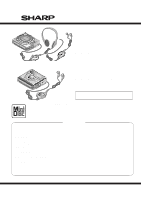
SERVICE MANUAL
SHARP
CORPORATION
No. SX891MDMS722U
This document has been published to be used
for after sales service only.
The contents are subject to change without notice.
• In the interests of user-safety the set should be restored to its
original condition and only parts identical to those specified be
used.
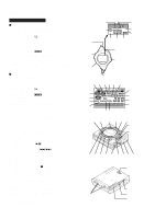
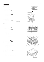
(Illustration: MD-MS721W)
(Illustration: MD-MS722/MS722C/MS722W)