Sharp MS722 Service Manual - Page 11
Disassembly, Installing The Top Cabinet - battery
 |
UPC - 074000410077
View all Sharp MS722 manuals
Add to My Manuals
Save this manual to your list of manuals |
Page 11 highlights
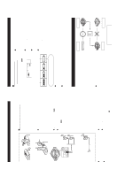
MD-MS722/C/W/MS721W DISASSEMBLY (A2)x2 Cares before disassembling ø1.4x2mm (A2)x1 ø1.4x2mm When assembling the machine after disassembling or Bottom Cabinet repair, observe the following requirements so as to (A2)x1 ensure safety and performance. ø1.4x2.5mm (B1)x1 ø1.4x2mm (A1)x1 1. Remove the batteries from the machine, and take out the mini-disc. 2. When assembling after repair, be sure to restore the initial location of wires. Since the screws are small, incorrect fixing may result in malfunction. 3. When repairing, pay utmost attention to static electricity of ICs. STEP REMOVAL PROCEDURE FIGURE Center Cabinet Pull Top Cabinet Figu re 11-1 (A2)x2 ø1.4x2mm (B1)x2 ø1.4x2mm 1 Bottom Cabinet 1. Battery Cover ......... (A1) x1 11-1 2. Screw A2) x6 2 Top Cabinet 1. Screw B1) x3 11-1 2. Flexble PWB B2) x2 11-2 Put the fold on the connector, and apply with the felt. Sagging may result in contact with the sheet metal. Felt Main PWB (C1)x1 ø1.7x2.5mm (B2)x1 3 Main PWB 1. Screw C1) x2 2. Flexble PWB ......... (C2) x2 3. Soldering C3) x4 11-2 (C1)x1 ø1.7x2.5mm (B2)x1 4 Mechanism Unit 1. Raise the rear part, and remove in the arrow direction. (Illustration: MD-MS722) 11-3 Pull Pull Pull Pull Pull Pull (C3)x3 (C2)x1* (C2)x1 Flexble PWB for optical pickup (C3)x1 Top Cabinet Caution: Carefully handle the main PWB and flexible PWB. After removing the flexible PWB (*1) for the optical pickup from the connector, do not touch directly the front end of flexible PWB with your hand so as to prevent damage of optical pickup by static electricity. Figure 11-2 Mechanism Unit ø1.4x2.5mm Cares when servicing: Be sure to use the screw with washer (Part code: LX-BZ0822AFFC, Distribution code: 124 970 0187). If a screw of different length is used by mistake, MD ejection may be disabled. Figure 11-4 Figure 11-3 INSTALLING THE TOP CABINET Insert the key flexible PWB at first into the clearance of center cabinet. Do not allow rise of upper cabinet. Figure 11-5 - 11 - Figure 11-6
-
 1
1 -
2
-
3
-
4
-
5
-
 6
6 -
 7
7 -
 8
8 -
 9
9 -
 10
10 -
 11
11 -
 12
12 -
 13
13 -
 14
14 -
 15
15 -
 16
16 -
17
-
18
-
19
-
20
-
21
-
22
-
23
-
24
-
25
-
26
-
27
-
28
-
29
-
30
-
31
-
32
-
33
-
34
-
35
-
36
-
37
-
38
-
39
-
40
-
41
-
42
-
43
-
44
-
45
-
46
-
47
-
48
-
49
-
50
-
51
-
52
-
53
-
54
-
55
-
56
 |
 |
