Sony BRCH900 Specification Sheet (CCFC-S200 & BRU-SF10 Specification) - Page 4
System Configurations, Pin Assignment and Connection, BRU-SF10
 |
View all Sony BRCH900 manuals
Add to My Manuals
Save this manual to your list of manuals |
Page 4 highlights
System Configurations (When the BRBK-HSD2 x1 is inserted into the BRU-SF10) BRC-Z330/-H900 Note: The BRBK-HD2 for the BRC-Z330/-H900 can not be used with the BRU-SF10. Pin Assignment and Connection BRU-SF10 VISCA RS-232C IN pin assignment 8 7 6 5 43 2 1 Pin No. 1 2 3 4 5 6 7 8 Name DTR DSR TXD GND RXD GND N.C. N.C. Signals Data Transmission Ready (INPUT) Data Set Ready (INPUT) Transmit Data (INPUT) Ground Receive Data (INPUT) Ground No Connection No Connection VISCA RS-232C OUT pin assignment 8 7 6 5 43 2 1 Pin No. 1 2 3 4 5 6 7 8 Name DTR DSR TXD GND RXD GND N.C. N.C. Signals Data Transmission Ready (OUTPUT) Data Set Ready (OUTPUT) Transmit Data (OUTPUT) Ground Receive Data (OUTPUT) Ground No Connection No Connection - 4 -
-
 1
1 -
 2
2 -
 3
3 -
 4
4 -
 5
5 -
 6
6 -
 7
7 -
 8
8 -
 9
9 -
 10
10 -
11
-
12
-
13
-
14
-
15
-
16
-
17
-
18
-
19
-
20
-
21
-
22
 |
 |

- 4 -
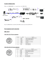
System Configurations
(When the BRBK-HSD2 x1 is inserted into the BRU-SF10)
Note: The BRBK-HD2 for the BRC-Z330/-H900 can not be used with the BRU-SF10.
Pin Assignment and Connection
BRU-SF10
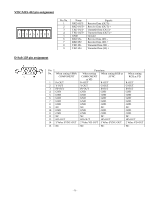
VISCA RS-232C IN pin assignment
VISCA RS-232C OUT pin assignment
Pin No.
Name
Signals
1
DTR
Data Transmission Ready (INPUT)
2
DSR
Data Set Ready (INPUT)
3
TXD
Transmit Data (INPUT)
4
GND
Ground
5
RXD
Receive Data (INPUT)
6
GND
Ground
7
N.C.
No Connection
8
N.C.
No Connection
Pin No.
Name
Signals
1
DTR
Data Transmission Ready (OUTPUT)
2
DSR
Data Set Ready (OUTPUT)
3
TXD
Transmit Data (OUTPUT)
4
GND
Ground
5
RXD
Receive Data (OUTPUT)
6
GND
Ground
7
N.C.
No Connection
8
N.C.
No Connection
2
3
4
5
6
7
8
1
2
3
4
5
6
7
8
1
BRC-Z330/-H900