Sony CDX-C5850 Installation Connections - Page 2
Installation
 |
View all Sony CDX-C5850 manuals
Add to My Manuals
Save this manual to your list of manuals |
Page 2 highlights
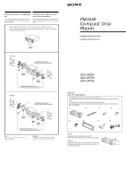
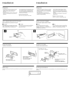
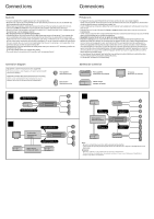
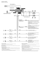
Installation Installation Precautions •Do not tamper with the four holes on the upper surface of the unit. They are used for tuner adjustments to be made only by service technicians. •Choose the installation location carefully so that the unit will not interfere with normal driving operations. •Avoid installing the unit in areas subject to dust, dirt, excessive vibration, or high temperatures, such as in direct sunlight or near heater ducts. •Use only the supplied mounting hardware for a safe and secure installation. Mounting angle adjustment Adjust the mounting angle to less than 60°. Précautions • Ne pas toucher les quatre orifices sur le panneau supérieur de l'appareil. Ils servent aux réglages du syntoniseur qui ne doivent être effectués que par un technicien. • Choisir soigneusement l'emplacement de l'installation afin que l'appareil ne gêne pas la conduite normale du véhicule. • Eviter d'installer l'appareil dans un endroit exposé à des températures élevées, comme en plein soleil ou à proximité d'une bouche d'air chaud, ou à de la poussière, saleté ou vibrations violentes. • Pour garantir un montage sûr, n'utiliser que le matériel fourni. Réglage de l'angle de montage Ajuster l'inclinaison à un angle inférieur à 60°. How to detach and attach the front panel Before installing the unit, detach the front panel. A To detach Before detaching the front panel, be sure to press (OFF). Press (RELEASE), then slide the front panel a little to the left, and pull it off towards you. B To attach Attach part a of the front panel to part b of the unit as illustrated and push the left side into position until it clicks. Retrait et pose de la façade Avant d'installer l'appareil, déposer la façade. A Retrait Avant de retirer la façade, ne pas oublier d'appuyer d'abord sur (OFF). Appuyez sur (RELEASE), puis faites glisser la façade légèrement vers la gauche et retirez-la à soi. B Pose Fixez la partie a de la façade sur la partie b de l'appareil, comme indiqué sur l'illustration, puis appuyez sur le côté gauche jusqu'au déclic. A (OFF) B a b (RELEASE) Mounting example Installation in the dashboard 1 2 182 mm TOP 1 With the TOP marking up Avec l'inscription TOP vers le haut 53 mm Bend these claws outward for a tight fit, if necessary. Plier ces griffes pour assurer une prise correcte si nécessaire. Exemple de montage Installation dans le tableau de bord To support the unit Pour installer l'appareil Dashboard Tableau de bord Fire wall Paroi ignifuge TOP 2 3 max. size M4 × 6 mm Dimension max. M4 × 6 mm 4 1 First attach 6 to the unit, then insert the unit into 1. 6 Fixez d'abord 6 sur l'appareil et introduisez ensuite l'appareil dans 1. Reset button When the installation and connections are complete, be sure to press the reset button with a ball-point pen, etc. Touche de réinitialisation Quand l'installation et les connexions sont terminées, appuyer sur la touche de réinitialisation avec un stylo à bille, etc.
-
 1
1 -
 2
2 -
 3
3 -
 4
4
 |
 |
