Sony CPD-1730 Operating Instructions (primary manual) - Page 6
Connections
 |
View all Sony CPD-1730 manuals
Add to My Manuals
Save this manual to your list of manuals |
Page 6 highlights
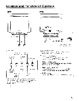
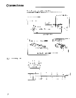
Connections Connect the power cord and the monitor cable. Be sure to turn the power of the unit off before making the connection. Rear of the CPD-1730 Microcomputer AC power cord (supplied) I to RGB OUT to AC IN Three-row D-sub 15 pin (male) Color monitor cable Align the plug with the receptacle. 2 Plug in and tighten the screws by hand. RGB Input Pin Assignment To disconnect the plug, loosen the screws. 1 234 5 O O O O O) 6 OOOOO10 00000 11 15 1 2 3 4 5 6 7 8. R G B GND GND GND GND GND 9 10 11 12 13 14 15 - GND GND - H SYNC V SYNC - 6
-
 1
1 -
 2
2 -
 3
3 -
 4
4 -
 5
5 -
 6
6 -
 7
7 -
 8
8 -
 9
9 -
 10
10 -
 11
11 -
 12
12 -
13
-
14
-
15
-
16
-
17
 |
 |

Connections
Connect
the
power
cord
and
the
monitor
cable.
Be
sure
to
turn
the
power
of
the
unit
off
before
making
the
connection.
Rear
of
the
CPD-1730
RGB
Input
Pin
Assignment
Microcomputer
AC
power
cord
(supplied)
I
to
RGB
OUT
to
AC
IN
Three
-row
D
-sub
15
pin
(male)
Color
monitor
cable
Align
the
plug
with
the
receptacle.
2
Plug
in
and
tighten
the
screws
by
hand.
To
disconnect
the
plug,
loosen
the
screws.
1
2
3
4
5
O
O O O
O)
6
OOOOO10
00000
11
15
1
2
3
4
5
6
7
8
.
R
G
B
GND
GND
GND
GND
GND
9
10
11
12
13
14
15
-
GND
GND
-
H
SYNC
V
SYNC
-
6