Sony HCD-HX7 Service Manual - Page 63
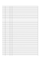
SWITCHING POWER BOARD, IC11 CXD9841P POWER CONTROL, Pin No., Pin Name, Description
 |
View all Sony HCD-HX7 manuals
Add to My Manuals
Save this manual to your list of manuals |
Page 63 highlights
HCD-HX3/HX5/HX7 SWITCHING POWER BOARD IC11 CXD9841P (POWER CONTROL) Pin No. 1 2 3 4 5 6 7 8 9 10 11 12 13 14 15 16 17 18 Pin Name VSENSE F/B CT RT GND PROTECT SS VC1 OCP VC2 P-GND VG (L) VB VS VG (H) - VD I/O Description I AC line voltage detection signal input terminal I Feed back signal input terminal for frequency modulation of oscillator I Connected to the external capacitor for oscillator duty/frequency setting I Connected to the external resistor for oscillator frequency setting - Ground terminal I Connected to the external capacitor for determines intermittent operation period when abnormal detection state I Connected to the external capacitor for soft start timing I Power supply terminal for control circuit "L": stop I Over current detection signal and didt protection signal input terminal O Power supply output terminal for driver - Ground terminal for low voltage side driver O Low voltage side driver drive signal output terminal - Not used O Power supply output terminal for high voltage side driver I High voltage side driver reference voltage input terminal O High voltage side driver drive signal output terminal - Not used I Terminal for drain-kick starting When starting, current is supplied directly from the rectification diode to VC1 63
-
 1
1 -
2
-
3
-
4
-
5
-
6
-
7
-
8
-
9
-
10
-
11
-
12
-
13
-
14
-
15
-
16
-
17
-
18
-
19
-
20
-
21
-
22
-
23
-
24
-
25
-
26
-
27
-
28
-
29
-
30
-
31
-
32
-
33
-
34
-
35
-
36
-
37
-
38
-
39
-
40
-
41
-
42
-
43
-
44
-
45
-
46
-
47
-
48
-
49
-
50
-
51
-
52
-
53
-
54
-
55
-
56
-
57
-
 58
58 -
 59
59 -
 60
60 -
 61
61 -
 62
62 -
 63
63 -
 64
64 -
 65
65 -
 66
66 -
 67
67 -
 68
68 -
69
-
70
-
71
-
72
-
73
-
74
-
75
-
76
-
77
-
78
-
79
-
80
-
81
-
82
-
83
-
84
-
85
-
86
-
87
-
88
-
89
-
90
 |
 |
