Sony KDE-42XBR950OL Operating Instructions - Page 26
After making all connections, connect the AC power cords supplied to wall, DISPLAY SIGNAL OUT jacks
 |
View all Sony KDE-42XBR950OL manuals
Add to My Manuals
Save this manual to your list of manuals |
Page 26 highlights
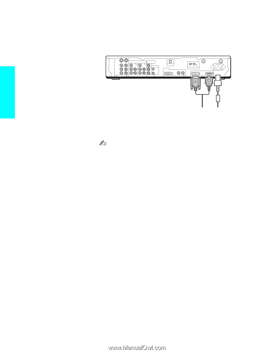
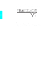
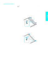
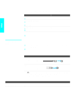
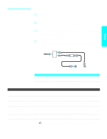
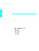
Setup 3 Install the display unit using an optional stand or rack unit. For details, refer to the operating instructions supplied with your stand or rack unit. 4 Connect the other end of display interface cable to the Media receiver unit's DISPLAY SIGNAL OUT jacks, and connect the AC power cord (supplied) to the media receiver unit's AC IN jack. S VIDEO VIDEO L AUDIO R 1 VIDEO IN HD/DVD IN SUB WOOFER (1080i/720p/480p/480i) OUT(VAR) Y 4Y 5 AUDIO AUDIO PB L PB L CONTROL S L IN PR R 3 PR R R OUT AUDIO OUT (VAR/FIX) OPTICAL OUT DVI-HDTV R - AUDIO - L S400 (TV/DV/MICROMV) i.LINK VHF/UHF CABLE WHITE BLACK ~ AC IN DVI-HDTV IN 6 DISPLAY SIGNAL OUT Tighten the screw slowly until the screw is stabilized. Display interface AC power cord cable (supplied) (supplied) 5 After making all connections, connect the AC power cords (supplied) to wall outlets. Be sure to use the supplied AC power cords. When connecting optional components, do not connect the AC power cords to wall outlets until you have completed making all connections. Do not tighten the screws too much. It may damage the screws. Handle the display interface cable with care. If you pull the cable by catching your feet on the cable, this unit may fall and cause injury. Do not use damaged cables, such as cables whose connectors are deformed. 24
-
 1
1 -
2
-
3
-
4
-
5
-
6
-
7
-
8
-
9
-
10
-
11
-
12
-
13
-
14
-
15
-
16
-
17
-
18
-
19
-
20
-
 21
21 -
 22
22 -
 23
23 -
 24
24 -
 25
25 -
 26
26 -
 27
27 -
 28
28 -
 29
29 -
 30
30 -
 31
31 -
32
-
33
-
34
-
35
-
36
-
37
-
38
-
39
-
40
-
41
-
42
-
43
-
44
-
45
-
46
-
47
-
48
-
49
-
50
-
51
-
52
-
53
-
54
-
55
-
56
-
57
-
58
-
59
-
60
-
61
-
62
-
63
-
64
-
65
-
66
-
67
-
68
-
69
-
70
-
71
-
72
-
73
-
74
-
75
-
76
-
77
-
78
-
79
-
80
-
81
-
82
-
83
-
84
-
85
-
86
-
87
-
88
-
89
-
90
-
91
-
92
-
93
-
94
-
95
-
96
-
97
-
98
-
99
-
100
-
101
-
102
-
103
-
104
-
105
-
106
-
107
-
108
-
109
-
110
-
111
-
112
-
113
-
114
-
115
-
116
-
117
-
118
-
119
-
120
-
121
-
122
-
123
-
124
-
125
-
126
-
127
-
128
-
129
-
130
-
131
-
132
 |
 |