Sony KP-61V85 Operating Instructions - Page 20
Connecting a DVD Player, Connecting a DVD Player with component video output connectors
 |
View all Sony KP-61V85 manuals
Add to My Manuals
Save this manual to your list of manuals |
Page 20 highlights
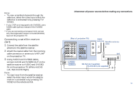
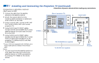
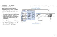
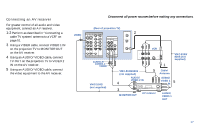
Installing and Connecting the Projection TV (continued) Connecting a DVD Player (Upper illustration) Using an AUDIO and S VIDEO cables, connect AUDIO and S VIDEO IN on the projection TV to AUDIO and S VIDEO OUT on the DVD Player (White-AUDIO Left, RedAUDIO Right). S VIDEO Disconnect all power sources before making any connections. (Rear of projection TV) IN VIDEO 1 VIDEO 3 VIDEO 4 VIDEO 5 S VIDEO VIDEO L (MONO) AUDIO R Y PB PR L AUDIO R OUT TV MONITOR AUDIO (VAR/FIX) VIDEO L (MONO) AUDIO R AUX TO CONVERTER VHF/UHF DVD LINE OUT S VIDEO OUT R-AUDIO 1-L VIDEO S-LINK DIGITAL OUT OPTICAL COAXIAL Connecting a DVD Player with component video output connectors (Lower illustration) 1 Using an AUDIO cable, connect AUDIO of LINE OUT on the DVD Player to AUDIO of VIDEO 4 or 5 IN on the projection TV (White-AUDIO Left, Red-AUDIO Right). 2 Using three yellow VIDEO cables, connect Y, PB, and PR of COMPONENT VIDEO OUT on the DVD Player to Y, PB, and PR of VIDEO 4 or 5 IN on the projection TV. Notes: • Since the high quality pictures on a DVD disc contain a lot of information, picture noise may appear. In this case, adjust "Noise Reduction" in the Video menu. (see "Noise Reduction" on page 34) • Some DVD Player terminals may be labeled differently. If so, connect as follows: Connect Y (green) to Y. Connect PB (blue) to CB, Cb or B-Y. Connect PR (red) to CR, Cr or R-Y. AUDIO-R S-LINK VIDEO 1 VIDEO 3 AUDIO-L VIDEO 4 IN VIDEO 5 S-LINK AUDIO TV MONITOR (VAR/FIX) OUT Audio/S video outputs Y PB PR (Rear of projection IN VIDEO 1 VIDEO 3 VIDEO 4 TV) S VIDEO Y PB VIDEO 5 VIDEO L (MONO) AUDIO R PR L AUDIO R RK-74A (not supplied) YC-15V/30V (not supplied) VMC-10HG (not supplied) Connect the DVD Player directly to the projection TV. Connecting the DVD Player through other video equipment will cause unwanted picture noise. OUT TV MONITOR AUDIO (VAR/FIX) VIDEO L (MONO) AUDIO R AUX TO CONVERTER VHF/UHF DVD LINE OUT S VIDEO OUT COMPONENT VIDEO OUT S-LINK DIGITAL OUT R-AUDIO 1-L VIDEO Y B-Y R-Y OPTICAL COAXIAL S-LINK VIDEO 1 VIDEO 3 VIDEO 4 IN VIDEO 5 S-LINK AUDIO TV MONITOR (VAR/FIX) OUT AUDIO-L AUDIO-R RK-74A (not supplied) 16
-
 1
1 -
2
-
3
-
4
-
5
-
6
-
7
-
8
-
9
-
10
-
11
-
12
-
13
-
14
-
 15
15 -
 16
16 -
 17
17 -
 18
18 -
 19
19 -
 20
20 -
 21
21 -
 22
22 -
 23
23 -
 24
24 -
 25
25 -
26
-
27
-
28
-
29
-
30
-
31
-
32
-
33
-
34
-
35
-
36
-
37
-
38
-
39
-
40
-
41
-
42
-
43
-
44
-
45
-
46
-
47
-
48
-
49
-
50
-
51
-
52
-
53
-
54
-
55
-
56
-
57
-
58
-
59
-
60
-
61
-
62
-
63
-
64
-
65
-
66
 |
 |
