Sony PCV-MXS20 System Reference Manual
Sony PCV-MXS20 - Vaio Desktop Computer Manual
 |
View all Sony PCV-MXS20 manuals
Add to My Manuals
Save this manual to your list of manuals |
Sony PCV-MXS20 manual content summary:
- Sony PCV-MXS20 | System Reference Manual - Page 1
i - Sony PCV-MXS20 | System Reference Manual - Page 2
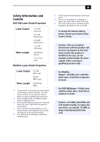
ii VAIO MX Computer System Reference Manual NOTICE © 2002 Sony Electronics Inc. Reproduction in whole or in part without written permission is prohibited. All rights reserved. This manual and the software described herein, in whole or in part, may not be reproduced, translated, or reduced to any - Sony PCV-MXS20 | System Reference Manual - Page 3
expose your desktop to rain or moisture. To avoid electrical shock, do not open the cabinet. Refer servicing to qualified personnel only. ❑ Never install modem or telephone wiring during a lightning storm. ❑ Never install telephone jacks in wet locations unless the jack is specifically designed for - Sony PCV-MXS20 | System Reference Manual - Page 4
iv VAIO MX Computer System Reference Manual ❑ Pour prévenir tout risque d'incendie ou d'électrocution, garder regarding your product or for the Sony Service Center nearest you, call 1-888-476-6972 in the United States or 1-800-961-7669 in Canada. Sony Computing Support can be reached at http://www - Sony PCV-MXS20 | System Reference Manual - Page 5
Declaration of Conformity Trade Name: SONY Model No.: PCV-MXS20 Responsible Party: Sony Electronics Inc. Address: 680 Kinderkamack Rd. Oradell, NJ 07649 Telephone: 201-930-6972 This phone number is for FCC-related matters only. This device complies with Part 15 of the FCC rules - Sony PCV-MXS20 | System Reference Manual - Page 6
If the trouble is causing harm to the telephone network, the telephone company may request that you remove the equipment from the network until the problem is resolved. Repair of this equipment should be made only by a Sony Service Center or Sony authorized agent. For the Sony Service Center nearest - Sony PCV-MXS20 | System Reference Manual - Page 7
of lithium batteries in household or business trash may be prohibited. For the Sony Service Center nearest you, call 1-888-476-6972 in the United States or by the manufacturer. Discard used batteries according to the manufacturer's instructions. ! The battery pack used in this device may present a - Sony PCV-MXS20 | System Reference Manual - Page 8
VAIO MX Computer System Reference Manual protection that the electrical ground connections of the power utility, telephone lines and internal metallic water conditions énoncées ci-dessus n'empêche pas la dégradation du service dans certaines situations. Les réparations de matériel homologué doivent ê - Sony PCV-MXS20 | System Reference Manual - Page 9
ii Safety Information and Caution iii Regulatory Information v FCC Part 68 vi Telephone Consumer Protection Act of 1991 (United States l'Industrie Canada viii Chapter 1 - Identifying Components 1 Front View...2 Drives ...3 Buttons and Switches 4 Indicators and receivers 6 Connectors 7 Rear - Sony PCV-MXS20 | System Reference Manual - Page 10
an Open I/O Slot 42 Installing a 3.5-inch Internal Hard Disk Drive 43 To identify additional hard disk space 47 Removing the Power Supply 48 Replacing the Power Supply 49 Chapter 4 - System Board 51 Memory Module (DDR-DIMM) Slots 52 Power Supply and Aux Power Headers 53 CLR CMOS Jumper 55 - Sony PCV-MXS20 | System Reference Manual - Page 11
7 - Specifications 79 Processors 79 Chipset ...79 AGP Bus ...79 PCI Bus ...79 Memory Modules 80 Memory Configurations 80 L2 Cache ...80 Graphics ...80 Audio ...81 Communications 81 Giga Pocket I/O 81 I/O and Expansion Slots 82 Hard Drives and Controllers 82 Optical Drive 82 System BIOS 83 - Sony PCV-MXS20 | System Reference Manual - Page 12
xii VAIO MX Computer System Reference Manual - Sony PCV-MXS20 | System Reference Manual - Page 13
Chapter 1 Identifying Components The following sections identify and describe each component that is visible from the exterior of the VAIO® MX computer. Internal components are identified in the appropriate section of this manual. 1 - Sony PCV-MXS20 | System Reference Manual - Page 14
2 VAIO MX Computer System Reference Manual Front View - Sony PCV-MXS20 | System Reference Manual - Page 15
to and from a MiniDisc media. Supports Net MD protocol for secure music transfers. Accomodates one Type I or Type II PCMCIA card. See Specifications sheet for details.* Accomodates a MagicGate Memory Stick media. * The Specifications sheet is supplied with your computer's original documentation. - Sony PCV-MXS20 | System Reference Manual - Page 16
4 VAIO MX Computer System Reference Manual Buttons and Switches Optical disc eject MiniDisc media eject Play Stop Power on/off Muting MUTING DISPLAY FUNCTION VOL PC CARD PHONE MIC i.LINK S400 MEMORY STICK USB Previous/Rewind Next/Fast Forward Function Display Volume control Button or switch - Sony PCV-MXS20 | System Reference Manual - Page 17
Previous/Rewind button Next/Fast Forward button Function button Display button Volume control buttons Description Skips to the previous track on the current playback of Selects the operation mode of the computer. Selects the display mode on the LCD display screen. Increases or decreases the volume. - Sony PCV-MXS20 | System Reference Manual - Page 18
6 VAIO MX Computer System Reference Manual Indicators and receivers Infrared receiver Power/Stand by MUTING DISPLAY FUNCTION VOL PC CARD PHONE MIC i.LINK S400 MEMORY STICK USB LCD display screen MagicGate Memory Stick media access Indicator or receiver Infrared receiver Power/Stand by - Sony PCV-MXS20 | System Reference Manual - Page 19
DISPLAY FUNCTION VOL PC CARD PHONE MIC i.LINK S400 MEMORY STICK USB USB1 port i.LINK port Connector Headphone jack on the back of the system. A 6-pin i.LINK connector can supply power from the computer to the device if the device also has a 6-pin i.LINK port. A 4-pin i.LINK connector - Sony PCV-MXS20 | System Reference Manual - Page 20
MX Computer System Reference Manual Rear View Mouse Keyboard USB2 Ethernet Printer/ Parallel i.LINK (IEEE 1394) Serial VGA Monitor DVI-D KEYBOARD MOUSE USB NETWORK ACT LINK PRINTER i.LINK S400 SERIAL OPTICAL FM ANTENNA (75 ) IN OUT MONITOR R L LINE DVI IN LINE OUT AUDIO S VIDEO - Sony PCV-MXS20 | System Reference Manual - Page 21
) or an S-video cable (optional). Connection for an audio cable (supplied). Connection for a video cable adapter (supplied) or an S-video cable (optional). Connection for an FM antenna. Connection for a digital audio or optical device. Connection for the supplied power cord. Connection for a TV - Sony PCV-MXS20 | System Reference Manual - Page 22
10 VAIO MX Computer System Reference Manual I/O Connectors The following section identifies the various I/O connectors. Keyboard and Mouse Ports The keyboard and mouse ports are physically identical and have the same pinout. - Sony PCV-MXS20 | System Reference Manual - Page 23
Identifying Components 11 Serial Port The serial port is a standard 9-pin DB-9 male port. 1 6 9 5 Printer/Parallel Port The printer/parallel port is a standard 25-pin DB-25 female port. 13 25 14 1 - Sony PCV-MXS20 | System Reference Manual - Page 24
12 VAIO MX Computer System Reference Manual VGA Monitor Port The monitor port is a standard 15-pin female high-density VGA-type port located on the AGP plug-in card. 10 15 5 11 1 6 DVI-D Port The DVI-D port is a 24-pin DVI-D port that can be attached to a Sony XGA LCD panel (PCVA-15XD2), - Sony PCV-MXS20 | System Reference Manual - Page 25
mm stereo mini-jacks, located at the front of the computer. Headphones Mic Connector Headphones Mic Description 1.0 Vrms (typical). from the wall, and the telephone jack is for connecting the computer to a telephone. Your computer has only one RJ-11 female phone jack if you have a HomePNA - Sony PCV-MXS20 | System Reference Manual - Page 26
the computer to a device if the device also has a 6-pin i.LINK port. The 6-pin port supplies 10 V to 12 V and a maximum power of 6 watts. ✍ i.LINK is a trademark of Sony used only to designate that a product contains an IEEE 1394 connection. The i.LINK connection may vary, depending on the software - Sony PCV-MXS20 | System Reference Manual - Page 27
for expansion. The AGP slot (No. 4) is occupied by an AGP card. See Specifications sheet for details.* Slot No. 4 (AGP card) Slot No. 3 (PCI slot) Slot No. 2 (Giga Pocket card) Slot No. 1 (V.90 compatible modem) * The Specifications sheet is supplied with your computer's original documentation. - Sony PCV-MXS20 | System Reference Manual - Page 28
16 VAIO MX Computer System Reference Manual - Sony PCV-MXS20 | System Reference Manual - Page 29
Chapter 2 Configuring Your System This chapter contains information on configuring your system. Configuring your system can consist of the following: ❑ Making changes to the BIOS settings. ❑ Making changes to the display's power management settings. 17 - Sony PCV-MXS20 | System Reference Manual - Page 30
18 VAIO MX Computer System Reference Manual Accessing the BIOS Setup Utility You must access the BIOS Setup Utility to make changes to the BIOS settings (see "CMOS Setup Options" on page 57 for information on BIOS settings). ! Before rebooting the system, save and close all open files, and exit open - Sony PCV-MXS20 | System Reference Manual - Page 31
Settings A display that has power management capability is designed to operate on reduced power or shut itself off after the system has been idle for a specified period of time. 1 From the Start menu, point to Settings, click Control Panel, then click Display. The Power Options Properties dialog box - Sony PCV-MXS20 | System Reference Manual - Page 32
20 VAIO MX Computer System Reference Manual 2 Select the power scheme that is most appropriate for the way you use your computer. To change a power scheme, change the settings for Turn off monitor, and Turn off hard disks, System standby, and System hibernates. The Turn off monitor option allows you - Sony PCV-MXS20 | System Reference Manual - Page 33
4 Click the Advanced tab. Configuring Your System 21 5 Select the desired settings. - Sony PCV-MXS20 | System Reference Manual - Page 34
22 VAIO MX Computer System Reference Manual 6 Click the Hibernate tab. 7 Select the settings most appropriate for your system. - Sony PCV-MXS20 | System Reference Manual - Page 35
23 8 Click the UPS tab. The UPS tab enables you to select and configure an Uninterruptible Power Supply (UPS) device for your system. ✍ A UPS device is an optional accessory not currently supplied with your system. 9 Select and configure the settings most appropriate for your system and click OK - Sony PCV-MXS20 | System Reference Manual - Page 36
24 VAIO MX Computer System Reference Manual - Sony PCV-MXS20 | System Reference Manual - Page 37
for upgrading, reconfiguring, and troubleshooting the components. ! Before opening the system unit, save and close all open files, exit all open applications, turn off the power to all attached peripheral devices, shut down the computer, and unplug the power cord. ✍ Your system's configuration may - Sony PCV-MXS20 | System Reference Manual - Page 38
VAIO MX Computer System Reference Manual Removing the Side Panel 1 Shut down your computer and turn off all peripheral devices, such as your printer. 2 Unplug your computer after you shut down your computer, the components may be too hot to touch. Wait until the internal parts of the system unit cool - Sony PCV-MXS20 | System Reference Manual - Page 39
Removing, Installing, and Replacing Components 27 Replacing the Side Panel 1 Carefully align the tabs on the side panel to the chassis frame. The side panel should lie flat against the chassis, with approximately 3/8 inch of clearance between the front edge of the side panel and the front of the - Sony PCV-MXS20 | System Reference Manual - Page 40
28 VAIO MX Computer System Reference Manual Removing a PCI Add-in Card ! Before opening the system unit, save and close all open files, exit all open applications, turn off the power to all attached peripheral devices, shut down the computer, and unplug the power cord. 1 Remove the side cover (see " - Sony PCV-MXS20 | System Reference Manual - Page 41
. Static electricity in your body may damage sensitive components on the card. As a precaution, touch any exposed metal part on the metal chassis (preferably the metal part on the power supply) before handling an add-in card to discharge any static electricity in your body. 6 If you do not replace - Sony PCV-MXS20 | System Reference Manual - Page 42
30 VAIO MX Computer System Reference Manual Installing a PCI Add-In Card ! Before opening the system unit, save and close all open files, exit all open applications, turn off the power to all attached peripheral devices, shut down the computer, and unplug the power cord. 1 Remove the side cover (see - Sony PCV-MXS20 | System Reference Manual - Page 43
, and Replacing Components 31 6 Attach any necessary cables to the card (see the instructions that came with the add-in card). 7 Replace the amplifier block unit to cover (see "Replacing the Side Panel" on page 27). 9 Turn on the computer and follow any instructions that came with the add-in card. - Sony PCV-MXS20 | System Reference Manual - Page 44
32 VAIO MX Computer System Reference Manual Replacing the Lithium Battery ! Before opening the system unit, save and close all open files, exit all open applications, turn off the power to all attached peripheral devices, shut down the computer, and unplug the power cord. You may need to replace the - Sony PCV-MXS20 | System Reference Manual - Page 45
10 Gently lift out the battery and dispose of it according to the instructions that came with the new battery. 11 Insert the new battery into the plus (+) side up, and press down until the battery is secure. ✍ The Sony CR2032 battery is recommended. Using a type of battery other than a CR2032 may - Sony PCV-MXS20 | System Reference Manual - Page 46
34 VAIO MX Computer System Reference Manual 15 Reconnect the power cord and turn on the computer. 16 If the error message "Error: Check date and time settings." appears during the reboot sequence, press F2 during the reboot process to access the BIOS Setup Utility. If no error message displays, the - Sony PCV-MXS20 | System Reference Manual - Page 47
devices, shut down the computer, and unplug the power cord. 1 Remove the side cover (see "Removing the Side Panel" on page 26). 2 Remove the power supply (see "Removing the Power Supply" on page 48). 3 Locate the memory module you wish to remove. Latch ✍ The memory modules are located beneath the - Sony PCV-MXS20 | System Reference Manual - Page 48
36 VAIO MX Computer System Reference Manual 4 Push down the handle on each side of the memory module to eject the module from its socket. ! Touch any exposed metal part of the chassis to discharge static electricity in your body before handling the memory module. 5 Grasp one edge of the memory - Sony PCV-MXS20 | System Reference Manual - Page 49
down the computer, and unplug the power cord. 1 Choose the size of the memory module and configuration as shown in the following table. Memory modules can vary in size and speed between sockets. The minimum memory size is 8 MB. The maximum memory size is 1 GB. The BIOS automatically detects the - Sony PCV-MXS20 | System Reference Manual - Page 50
exposed metal part on the metal chassis (preferably the metal part on the power supply) before handling an add-in card to discharge any static electricity in your body. ! Do not remove the Giga Pocket card (located in PCI slot No. 2) unless directed by a service technician. The Giga Pocket card is - Sony PCV-MXS20 | System Reference Manual - Page 51
, and Replacing Components 39 9 Align the module over the appropriate socket, noting the location of pin 1 on the module and pin 1 on the socket. Latch Memory module (DDR-DIMM) 111 Pin 1 side 10 Carefully but firmly insert the edge of the module into the socket. 11 Press down firmly and evenly - Sony PCV-MXS20 | System Reference Manual - Page 52
slot. 13 Replace the power supply (see "Replacing the Power Supply" on page 49). 14 Replace the side cover (see "Replacing the Side Panel" on page 27). 15 Reconnect the power cord and turn on the computer. Your computer automatically recognizes the extra memory and configures itself accordingly when - Sony PCV-MXS20 | System Reference Manual - Page 53
! Before opening the system unit, save and close all open files, exit all open applications, turn off the power to all attached peripheral devices, shut down the computer, and unplug the power cord. 1 Remove the side cover (see "Removing the Side Panel" on page 26). 2 Locate the slot whose cover you - Sony PCV-MXS20 | System Reference Manual - Page 54
42 VAIO MX Computer System Reference Manual Covering an Open I/O Slot ! Before opening the system unit, save and close all open files, exit all open applications, turn off the power to all attached peripheral devices, shut down the computer, and unplug the power cord. Slot covers prevent air from - Sony PCV-MXS20 | System Reference Manual - Page 55
to all attached peripheral devices, shut down the computer, and unplug the power cord. 1 Configure the jumpers on the new drive as a slave device (see your drive's documentation for configuration instructions). Power connector Jumpers Drive connector 2 Remove the side cover (see "Removing the - Sony PCV-MXS20 | System Reference Manual - Page 56
44 VAIO MX Computer System Reference Manual 3 Disconnect the drive connector (A in diagram). Drive connectors (A) Power supply connectors (B) Disk drive holder 4 Disconnect the power connector (B in diagram). - Sony PCV-MXS20 | System Reference Manual - Page 57
Installing, and Replacing Components 45 5 Pull out on the tab (C) that secures the drive holder to the chassis. Tab (C) Disk drive holder (D) 6 Slide the disk drive holder (D) holder up and out. 7 Slide the new drive into the bottom part of the drive holder and align the holes on each side of the - Sony PCV-MXS20 | System Reference Manual - Page 58
46 VAIO MX Computer System Reference Manual 10 Push in on the tab (A) to securely latch the holder to the chassis. Power supply connectors (D-inner, E-outer) Drive connectors (B-inner, C-outer) Tab (A) Disk drive holder 11 Connect the inner drive cable connector (B) to the first drive. 12 Connect - Sony PCV-MXS20 | System Reference Manual - Page 59
the Unallocated area of the drive and then right-click to display the shortcut menu. 7 Select New Partition. The New Partition wizard appears. 8 Follow the onscreen instructions to complete the process. The Windows® XP operating system recognizes the new hard disk drive and applies the NTFS format - Sony PCV-MXS20 | System Reference Manual - Page 60
48 VAIO MX Computer System Reference Manual Removing the Power Supply You remove the main power supply before you insert a memory module (see "Installing System Memory" on page 37). ! Before opening the system unit, save and close all open files, exit all open applications, turn off the power to all - Sony PCV-MXS20 | System Reference Manual - Page 61
Removing, Installing, and Replacing Components 49 Replacing the Power Supply 1 Rotate the power supply down and slide it down along the rails on each side of the chassis opening. 2 Replace the screw that secures the power supply to the rear of the chassis. - Sony PCV-MXS20 | System Reference Manual - Page 62
50 VAIO MX Computer System Reference Manual - Sony PCV-MXS20 | System Reference Manual - Page 63
board. Keyboard, Mouse CPU Fan Memory Stick Connector Processor Memory USB3, USB4, Ethernet Printer, i.LINK 1394 Header 2 Serial Port, Mic In, Line In, Line Out 1394 Header 3 Video (not used) Aux-in Power Supply Fan Aux Power Supply Power Supply Secondary IDE Primary IDE Diskette Battery - Sony PCV-MXS20 | System Reference Manual - Page 64
DDR-DIMM1 DDR-DIMM2 52 VAIO MX Computer System Reference Manual Memory Module (DDR-DIMM) Slots Both sides of each Double-data rate, Dual Inline Memory Module (DDR-DIMM) look very similar. The side with pin 1 has a small "1" to the left of pin 1. Be sure to orient the memory module correctly in the - Sony PCV-MXS20 | System Reference Manual - Page 65
power supply header labelled P1 . 2 4 1 3 10 20 1 11 Power Supply header Pin Signal Name 1 +3.3 V 2 +3.3 V 3 Ground 4 +5 V 5 Ground 6 +5 V 7 Ground 8 PWRGD (Power Good) 9 +5 VSB 10 +12 V 11 +3.3 V 12 -12 V 13 Ground 14 PS-ON# (power supply remote on/off control - Sony PCV-MXS20 | System Reference Manual - Page 66
54 VAIO MX Computer System Reference Manual Power Supply header (Continued) Pin Signal Name 17 Ground 18 No Connection 19 +5 V 20 +5 V Aux Power header Pin Signal Name 1 Ground 2 Ground 3 +12 V 4 +12 V - Sony PCV-MXS20 | System Reference Manual - Page 67
Jumper The CLR CMOS Jumper clears the BIOS password setting. CLR CMOS 3 2 1 CLR CMOS Jumper settings Jumper Plug Position 2-3 1-2 Function Normal Clear CMOS Password ✍ The configuration jumpers should never need changing unless otherwise directed by a technical support or service technician. - Sony PCV-MXS20 | System Reference Manual - Page 68
56 VAIO MX Computer System Reference Manual - Sony PCV-MXS20 | System Reference Manual - Page 69
BIOS Setup Utility (see "Accessing the BIOS Setup Utility" on page 18). The Award BIOS setup has five menu items on the menu bar. These are: ❑ Main ❑ Advanced ❑ Power are shown without brackets directly below the default option in this guide. The available options are listed in the order they occur - Sony PCV-MXS20 | System Reference Manual - Page 70
58 VAIO MX Computer System Reference Manual Press F10 to save the changes and exit, or press Esc to discard the changes. Follow the on-screen prompts for other choices. The bottom of the screen presents a summary of the keys to use for navigation and control. - Sony PCV-MXS20 | System Reference Manual - Page 71
Secondary Slave (see "IDE Sub-Menus" on page 60) Supervisor Password [Disabled] User Password [Disabled] Installed Memory See Specifications sheet for details.* BIOS Revision/Version 1003 (depends on model) * The Specifications sheet is supplied with your computer's original documentation. - Sony PCV-MXS20 | System Reference Manual - Page 72
60 VAIO MX Computer System Reference Manual IDE Sub-Menus Type Translation Method* Cylinders† Heads model) [Maximum] Disabled 2 Sectors 4 Sectors 8 Sectors 16 Sectors 32 Sectors [4] [5] [Auto] Floppy Hard Disk * This option appears when Type is set to User Type HDD. † This option appears when Type - Sony PCV-MXS20 | System Reference Manual - Page 73
CMOS Setup Options 61 Advanced Screen CPU Internal Frequency [2000 MHz]* I/O Device Configuration (see "I/O Device Configuration Sub-Menu" on page 62) PCI Configuration (see "PCI Configuration Sub-Menu" on page 63) * Depends on model. - Sony PCV-MXS20 | System Reference Manual - Page 74
62 VAIO MX Computer System Reference Manual I/O Device Configuration Sub-Menu Onboard AC97 Audio Controller [Disabled] Enabled Onboard 1394 Controller [Enabled] Disabled Onboard Lan Controller [Enabled] Disabled Onboard Serial Port 1 [3F8H/IRQ4] 2F8H/IRQ3 3E8H/IRQ4 2E8H/IRQ10 Disabled - Sony PCV-MXS20 | System Reference Manual - Page 75
PCI Configuration Sub-Menu Slot 1 IRQ to Slot 3 IRQ VGA BIOS Sequence Onboard LAN Boot ROM CMOS Setup Options 63 [Auto] NA 3 4 5 7 9 10 11 12 14 15 [PCI/AGP] AGP/PCI [Disabled] Enabled - Sony PCV-MXS20 | System Reference Manual - Page 76
64 VAIO MX Computer System Reference Manual Power Screen Power Up Control AC PWR Loss Restart PWR Up On Modem Act Wake On LAN Hardware Monitor MB Temperature CPU Temperature CPU Fan Speed Power Fan Speed VCORE Voltage +3.3V Voltage +5V Voltage +12V Voltage -12V Voltage -5V Voltage [Disabled] - Sony PCV-MXS20 | System Reference Manual - Page 77
Boot Screen 1. ATAPI CD-ROM 2. Removable Device 3. IDE Hard Drive 4. Other Boot Device Silent Boot CMOS Setup Options 65 [(displays installed drive)] Disabled [Legacy Floppy] LS120 ZIP ATAPI MO USB FDD USB ZIP [(displays installed drive)] Disabled [Disabled] INT18 Device (Network) SCSI Boot - Sony PCV-MXS20 | System Reference Manual - Page 78
66 VAIO MX Computer System Reference Manual Exit Screen Exit Saving Changes Exit Discarding Changes Load Setup Defaults Discard Changes Save Changes - Sony PCV-MXS20 | System Reference Manual - Page 79
information on the following subjects: ❑ User and Supervisor password ❑ Beep code error messages ❑ PCI configuration status and error messages ❑ DMA channel assignments ❑ System I/O address map ❑ Memory map ❑ IRQ summary 67 - Sony PCV-MXS20 | System Reference Manual - Page 80
68 VAIO MX Computer System Reference Manual User and Supervisor Passwords The system allows you to specify up to two passwords (a User password and a Supervisor password) in the CMOS Setup Utility. The - Sony PCV-MXS20 | System Reference Manual - Page 81
, a single short beep signifies that the system is OK. Other beep patterns signify errors. The number of beeps indicates the specific error that occurred. The Sony Online Support technical representative needs to know how many beeps your system produces if there is an error, so be sure to count the - Sony PCV-MXS20 | System Reference Manual - Page 82
70 VAIO MX Computer System Reference Manual PCI Configuration Status and Error Messages The following is a list of status and error messages that may appear on your system from time to time. Message Floppy Disk Controller Resource Conflict NVRAM Checksum Error, NVRAM Cleared NVRAM Cleared By - Sony PCV-MXS20 | System Reference Manual - Page 83
Miscellaneous Technical Information 71 Static Device Resource Conflict System Board Device Resource Conflict A non-Plug and Play ISA card has requested a resource that is already in use. A non-Plug and-Play ISA card has requested a resource that is already in use. - Sony PCV-MXS20 | System Reference Manual - Page 84
72 VAIO MX Computer System Reference Manual DMA Channel Assignments This shows the factory default values. The Windows® operating system reassigns resources to best meet the needs of a particular configuration. DMA Channel 02 04 Default Assignment Standard floppy disk controller. Direct memory - Sony PCV-MXS20 | System Reference Manual - Page 85
0x00000044-0x0000005F Description PCI bus Direct memory access controller PCI bus Intel® 82845 Processor to AGP Controller nVIDIA GeForce2 MX with external TMDS (Sony) Intel® 82845 Processor to AGP Controller nVIDIA GeForce2 MX with external TMDS (Sony) Sony MPEG2 Encoder Board (WDM) Ricoh R/RL - Sony PCV-MXS20 | System Reference Manual - Page 86
Motherboard resources Motherboard resources Motherboard resources Motherboard resources Motherboard resources Motherboard resources Motherboard resources Programmable interrupt controller Programmable interrupt controller Direct memory access controller Direct memory access controller Direct memory - Sony PCV-MXS20 | System Reference Manual - Page 87
Miscellaneous Technical Information 75 Memory Map Address range 0x0000-0x9FFFF 0xF0000- AGP Controller nVIDIA GeForce2 MX with external TMDS (Sony) Intel® 82845 Processor to AGP Controller Intel® 82845 Processor to AGP Controller nVIDIA GeForce2 MX with external TMDS (Sony) Sony MPEG2 Encoder - Sony PCV-MXS20 | System Reference Manual - Page 88
76 VAIO MX Computer System Reference Manual Address range 0xFFDFCF00-0xFFDFCFFF 0xED000000-0xED0000FF Texas Instruments OHCI Compliant IEEE 1394 Host Controller Texas Instruments OHCI Compliant IEEE 1394 Host Controller Motherboard resources Motherboard resources ✍ I/O addresses that may be - Sony PCV-MXS20 | System Reference Manual - Page 89
SMBus Controller - 2443 3 USB Audio Device 4 Communications Port (COM1) 6 Standard Floppy Disk Controller 7 Controller 9 Sony MPEG2 Encoder Board (WDM) 9 WDM Communication Device 9 Intel® 82801BA/BAM USB Universal Host Controller 1 9 Intel® 82801BA/BAM USB Universal Host Controller - Sony PCV-MXS20 | System Reference Manual - Page 90
78 VAIO MX Computer System Reference Manual - Sony PCV-MXS20 | System Reference Manual - Page 91
AGP Bus AGP interface specification, version 2.0 (supports 2x/4x) 1 AGP slot PCI Bus PCI Level 2.2, 33 MHz zero wait state 3 PCI slots - not all PCI slots are available. (See Specifications sheet for details.)* * The Specifications sheet is supplied with your computer's original documentation. 79 - Sony PCV-MXS20 | System Reference Manual - Page 92
. Use only PC2100 (266 MHz) supported memory. Your system does not support EDO, buffered/unbuffered SDR-SDRAM, or PC100/133 SDRAM memory modules. L2 Cache Installed 256 KB or 512 KB of Advanced Transfer cache Graphics AGP Controller* Video memory See Specifications sheet for details.** See - Sony PCV-MXS20 | System Reference Manual - Page 93
maximum 400 Mbps, OHCI chip set * This modem is capable of downloading at 56 Kbps. Your phone service, online service, or Internet Service Provider may not support this technology or operate at this speed. Giga Pocket I/O Rear Audio In L/R S-Video/Video In S-Video/Video Out Audio Out L/R VHF/UHF - Sony PCV-MXS20 | System Reference Manual - Page 94
and Controllers Drive IDE hard drive* EIDE controller Description 120 GB C = 16 GB / D = 104 GB Supports up to four EIDE drives (supports PIO Mode 4 EIDE drives and Ultra DMA/100 Mode drives) * Bus-mastering EIDE driver installed. Optical Drive Drive DVD-RW drive Description See Specifications - Sony PCV-MXS20 | System Reference Manual - Page 95
Specifications 83 System BIOS Make and model ROM Passwords Power management Advanced features Plug and Play devices Special features Award-based 2 Mb flash-ROM* User and supervisor passwords supported APM 1.2 ACPI-1.0 compliant hardware for use with APM and PNP BIOS APIs Supported with steerable - Sony PCV-MXS20 | System Reference Manual - Page 96
84 VAIO MX Computer System Reference Manual - Sony PCV-MXS20 | System Reference Manual - Page 97
screen 64 screens 57 BIOS specifications 83 C chipset specifications 79 CLR CMOS Jumper 55 CMOS - See Also BIOS CMOS Setup Utility 18 codes, beeps 69 communications, specifications 81 computer lithium battery vii configuring power management 19 connectors i.LINK 7 monitor 12 power 53 USB 7 cover 27 - Sony PCV-MXS20 | System Reference Manual - Page 98
86 VAIO MX Computer System Reference Manual G Giga Pocket specifications 81 graphics controller - See graphics graphics specifications 80 H hard drive specifications 82 I i.LINK connector 7 I/O connectors i.LINK 14 keyboard and mouse 10 mic, line in, headphones 13 monitor 12 printer port 11 serial - Sony PCV-MXS20 | System Reference Manual - Page 99
See I/O slot slot cover, removing 41 specifications AGP bus 79 audio 81 BIOS 83 chipset 79 communications 81 Giga Pocket 81 graphics 80 hard drives and controllers 82 I/O and expansion slots 82 L2 cache 80 memory configurations 80 Index 87 memory module 80 optical drives 82 PCI bus 79 processor 79 - Sony PCV-MXS20 | System Reference Manual - Page 100
88 VAIO MX Computer System Reference Manual
-
 1
1 -
 2
2 -
 3
3 -
 4
4 -
 5
5 -
 6
6 -
 7
7 -
8
-
9
-
10
-
11
-
12
-
13
-
14
-
15
-
16
-
17
-
18
-
19
-
20
-
21
-
22
-
23
-
24
-
25
-
26
-
27
-
28
-
29
-
30
-
31
-
32
-
33
-
34
-
35
-
36
-
37
-
38
-
39
-
40
-
41
-
42
-
43
-
44
-
45
-
46
-
47
-
48
-
49
-
50
-
51
-
52
-
53
-
54
-
55
-
56
-
57
-
58
-
59
-
60
-
61
-
62
-
63
-
64
-
65
-
66
-
67
-
68
-
69
-
70
-
71
-
72
-
73
-
74
-
75
-
76
-
77
-
78
-
79
-
80
-
81
-
82
-
83
-
84
-
85
-
86
-
87
-
88
-
89
-
90
-
91
-
92
-
93
-
94
-
95
-
96
-
97
-
98
-
99
-
100
 |
 |