Sony PCV-RX640 System Reference Manual - Page 61
System Board
 |
View all Sony PCV-RX640 manuals
Add to My Manuals
Save this manual to your list of manuals |
Page 61 highlights
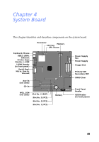
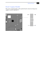
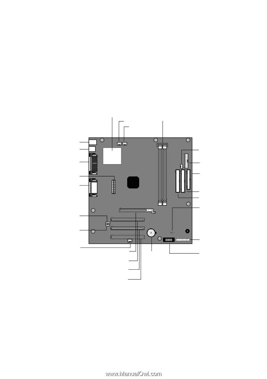
Chapter 4 System Board This chapter identifies and describes components on the system board. Processor Memory CPU Fan CPU Therm Keyboard, Mouse USB3, USB4, Ethernet Printer (top) Monitor, i.LINK i.LINK Header (to front panel) Serial (top) Mic in, Line in, Line out Aux-In (not used) CD-In WOL_CON (not used) Slot No. 4 (AGP) Slot No. 3 (PCI) Slot No. 2 (PCI) Slot No. 1 (PCI) Battery Power Supply Fan Power Supply Floppy Disk Primary IDE Secondary IDE CMOS Clear Front Panel Header USB Header (to front panel) 49
-
 1
1 -
2
-
3
-
4
-
5
-
6
-
7
-
8
-
9
-
10
-
11
-
12
-
13
-
14
-
15
-
16
-
17
-
18
-
19
-
20
-
21
-
22
-
23
-
24
-
25
-
26
-
27
-
28
-
29
-
30
-
31
-
32
-
33
-
34
-
35
-
36
-
37
-
38
-
39
-
40
-
41
-
42
-
43
-
44
-
45
-
46
-
47
-
48
-
49
-
50
-
51
-
52
-
53
-
54
-
55
-
 56
56 -
 57
57 -
 58
58 -
 59
59 -
 60
60 -
 61
61 -
 62
62 -
 63
63 -
 64
64 -
 65
65 -
 66
66 -
67
-
68
-
69
-
70
-
71
-
72
-
73
-
74
-
75
-
76
-
77
-
78
-
79
-
80
-
81
-
82
-
83
-
84
-
85
-
86
-
87
-
88
-
89
-
90
-
91
-
92
 |
 |
49
Chapter 4
System Board
This chapter identifies and describes components on the system board.
Keyboard, Mouse
USB3, USB4,
Printer (top)
Monitor, i.LINK
i.LINK Header
(to front panel)
Serial (top)
Mic in, Line in,
CD-In
Aux-In
(not used)
Slot No. 4 (AGP)
Slot No. 3 (PCI)
Slot No. 2 (PCI)
Slot No. 1 (PCI)
Battery
CMOS Clear
Processor
CPU Fan
Memory
Power Supply
Power Supply
Secondary IDE
Primary IDE
Floppy Disk
USB Header
(to front panel)
WOL_CON
(not used)
Front Panel
Line out
Header
Fan
CPU Therm
Ethernet