Sony STR-DB840 Operating Instructions - Page 13
CONTROL A1, hookup, S-LINK CONTROL S hookup, Models of area code U, CA only, Receiver, VCR 1, player
 |
View all Sony STR-DB840 manuals
Add to My Manuals
Save this manual to your list of manuals |
Page 13 highlights
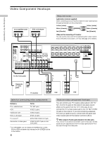
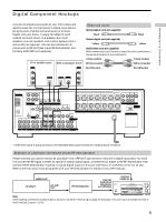
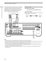
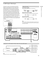
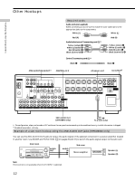
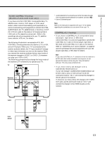
Hooking Up the Components S-LINK CONTROL S hookup (Models of area code U,CA only) If you have a S-LINK CONTROL S-compatible Sony TV, satellite tuner, monitor, DVD player or VCR, use an audio/video/control S connecting cord (supplied) or a control S connecting cord (supplied) to connect the CTRL S (STATUS) IN (for TV, satellite tuner, or monitor) or OUT (for VCR, etc.) jack on the receiver to the appropriate SLINK jack on the respective component. Refer to the operating instructions supplied with your TV, satellite tuner, monitor, VCR, etc., for details. The following illustration is an example of S-LINK CONTROL S hookups between the receiver, a TV, a VCR, and a DVD player. When your TV is connected to the receiver as shown below, the TV input mode will change to video input whenever you turn on the receiver. When you connect the receiver as shown below, input mode of the receiver changes to VIDEO 1 or DVD/LD whenever you play your VCR or DVD. The following connections also change the input mode of the receiver to TV whenever you operate your TV. TV S-LINK OUT IN E VIDEO IN D AUDIO OUT B A C Receiver ** CTRL S IN ** CTRL S STATUS IN CTRL S OUT CTRL S OUT S-VIDEO OUT VIDEO MONITOR S-VIDEO S-VIDEO IN IN VIDEO VIDEO AUDIO AUDIO IN IN S-VIDEO S-VIDEO OUT IN VIDEO VIDEO AUDIO AUDIO OUT IN * Audio/video/control S connecting cord (Pull the video cord away from the supplied audio/video/control S cable for connection A.) ** Control S connecting cord Note Refer to the instructions supplied with your TV for details regarding the operations you can control from your TV. CONTROL A1 hookup • If you have a CONTROL A1 compatible Sony CD player, tape deck, or MD deck Use a CONTROL A1 cord (not supplied) to connect the CONTROL A1 jack on the CD player, tape deck, or MD deck to the CONTROL A1 jack on the receiver. Refer to "CONTROL A1 Control System" on page 54 and the operating instructions supplied with your CD player, tape deck, or MD deck for details. Note If you make CONTROL A1 connections from the receiver to an MD deck that is also connected to a computer, do not operate the receiver while using the "Sony MD Editor" software. This may cause a malfunction. • If you have a Sony CD changer with a COMMAND MODE selector If your CD changer's COMMAND MODE selector can be set to CD 1, CD 2, or CD 3, be sure to set the command mode to "CD 1" and connect the changer to the CD jacks on the receiver. If, however, you have a Sony CD changer with VIDEO OUT jacks, set the command mode to "CD 2" and connect the changer to the VIDEO 2 jacks on the receiver. VCR 1 TV/SAT DVD/LD VIDEO 1 * OUTPUT VIDEO OUT S-LINK IN AUDIO OUT DVD player S-LINK IN * OUTPUT VIDEO OUT AUDIO OUT 13
-
 1
1 -
2
-
3
-
4
-
5
-
6
-
7
-
 8
8 -
 9
9 -
 10
10 -
 11
11 -
 12
12 -
 13
13 -
 14
14 -
 15
15 -
 16
16 -
 17
17 -
 18
18 -
19
-
20
-
21
-
22
-
23
-
24
-
25
-
26
-
27
-
28
-
29
-
30
-
31
-
32
-
33
-
34
-
35
-
36
-
37
-
38
-
39
-
40
-
41
-
42
-
43
-
44
-
45
-
46
-
47
-
48
-
49
-
50
-
51
-
52
-
53
-
54
-
55
-
56
-
57
-
58
-
59
-
60
-
61
-
62
-
63
-
64
 |
 |
