TP-Link T1500G-10MPS T1500G-10MPSUN V1 Installation Guide
TP-Link T1500G-10MPS Manual
 |
View all TP-Link T1500G-10MPS manuals
Add to My Manuals
Save this manual to your list of manuals |
TP-Link T1500G-10MPS manual content summary:
- TP-Link T1500G-10MPS | T1500G-10MPSUN V1 Installation Guide - Page 1
Business Networking Solution Installation Guide JetStream 8-Port Gigabit Smart PoE+Switch with 2 SFP Slots T1500G-10MPS - TP-Link T1500G-10MPS | T1500G-10MPSUN V1 Installation Guide - Page 2
- TP-Link T1500G-10MPS | T1500G-10MPSUN V1 Installation Guide - Page 3
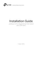
frequency energy and, if not installed and used in accordance with the instruction manual, may cause harmful interference to radio communications. Operation of this equipment in electric shock and voiding the limited warranty. If you need service, please contact us. • Avoid water and wet locations. - TP-Link T1500G-10MPS | T1500G-10MPSUN V1 Installation Guide - Page 4
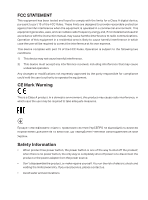
BSMI Notice Industry Canada Statement CAN ICES-3 (A)/NMB-3(A) Explanation of the symbols on the product label Symbol Explanation AC voltage RECYCLING This product bears the selective sorting symbol for Waste electrical and electronic equipment (WEEE). This means that this product must be - TP-Link T1500G-10MPS | T1500G-10MPSUN V1 Installation Guide - Page 5
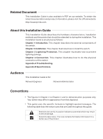
Related Document This Installation Guide is also available in PDF on our website. To obtain the latest documentation and product information, please visit the official website: http://www.tp-link.com About this Installation Guide This Installation Guide describes the hardware characteristics, - TP-Link T1500G-10MPS | T1500G-10MPSUN V1 Installation Guide - Page 6
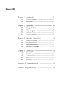
Reasonably 10 3.2 Connect to Ground 12 3.3 Equipotential Bonding 13 3.4 Use Lightning Arrester 14 Chapter 4 Connection 16 4.1 Ethernet Port 16 4.2 Verify Installation 16 4.3 Power On 16 4.4 Initialization 17 Appendix A Troubleshooting--------- 18 Appendix B Specifications---------- 19 - TP-Link T1500G-10MPS | T1500G-10MPSUN V1 Installation Guide - Page 7
Smart PoE+ Switch Chapter 1 Introduction 1.1 Product Overview T1500G-10MPS is compliant with the IEEE802.3 Ethernet protocols. The switch is equipped with powerful management interface, via which system, port, network, VLAN and priority can be configured. They provide a variety of service features - TP-Link T1500G-10MPS | T1500G-10MPSUN V1 Installation Guide - Page 8
Smart PoE+ Switch LEDs T1500G-10MPS has an LED mode switch button which is for switching the LED status indication. When the Speed LED is on, the port LED is indicating the data transmission status. When the PoE LED is on, the port LED is indicating the power supply status. By default, the Speed - TP-Link T1500G-10MPS | T1500G-10MPSUN V1 Installation Guide - Page 9
software setting to its factory default settings. 10/100/1000Mbps RJ45 Port and PoE Port Designed to connect to the device with a bandwidth of 10Mbps, 100Mbps or 1000Mbps. Each has a corresponding Speed or PoE LED. SFP Port Designed to install the SFP module. T1500G-10MPS features 2 SFP transceiver - TP-Link T1500G-10MPS | T1500G-10MPSUN V1 Installation Guide - Page 10
Smart PoE+ Switch ■■ Rear Panel The rear panel of T1500G-10MPS is shown as the following figure. Kensington Security Slot Power Socket Grounding Terminal Figure 1-2 Rear Panel of T1500G-10MPS Kensington Security Slot Secure the lock (not provided) into the security slot to prevent the device from - TP-Link T1500G-10MPS | T1500G-10MPSUN V1 Installation Guide - Page 11
Smart PoE+ Switch Chapter 2 Installation 2.1 Package Contents Make sure that the package contains the following items. If any of the listed items is damaged or missing, please contact your distributor. One Switch One Power Cord This Installation Guide Business Networking Solution Installation - TP-Link T1500G-10MPS | T1500G-10MPSUN V1 Installation Guide - Page 12
Smart PoE+ Switch ■■ Site Requirements To ensure normal operation and long service life of the device, please install it circuit board. To avoid the effect of static electricity on the operation of the Switch, please attach much importance to the following items: ■■ Dust the device regularly, and - TP-Link T1500G-10MPS | T1500G-10MPSUN V1 Installation Guide - Page 13
Smart PoE+ Switch ■■ Keep the device far from high-frequency, strong-current devices, , please note the following items: ■■ The rack or workbench is flat and stable, and sturdy enough to support the weight of 5.5kg at least. ■■ The rack or workbench has a good ventilation system. The equipment room - TP-Link T1500G-10MPS | T1500G-10MPSUN V1 Installation Guide - Page 14
Smart PoE+ Switch Note: These tools are not provided with our product. If needed, please self purchase them. 2.4 Product Installation ■■ Desktop Installation To install the device on the desktop, please follow the steps: 1. Set the device on a flat surface strong enough to support the instructions - TP-Link T1500G-10MPS | T1500G-10MPSUN V1 Installation Guide - Page 15
Smart PoE+ Switch 3. After the brackets are attached to the device, use suitable screws (not provided) to secure the brackets to the rack, as illustrated in the following - TP-Link T1500G-10MPS | T1500G-10MPSUN V1 Installation Guide - Page 16
Smart PoE+ Switch Chapter 3 Lightning Protection 3.1 Cabling Reasonably In the actual network be grounded. Before connecting the cable to the device, install a signal lightning arrester on the corresponding port. ■■ It's not necessary to pave STP cables through pipes. The shielded layer of STP cable - TP-Link T1500G-10MPS | T1500G-10MPSUN V1 Installation Guide - Page 17
Smart PoE+ Switch ■■ Requirements for Cabling Indoors When cabling indoors, keep a certain between Ethernet cable and other pipelines are shown in the table. Other Pipelines Down-conductor PE Service pipe Compressed air pipe Thermal pipe (not wrapped) Thermal pipe (wrapped) Gas pipe Ethernet Cable - TP-Link T1500G-10MPS | T1500G-10MPSUN V1 Installation Guide - Page 18
Smart PoE+ Switch Cable 2~5kVA powerline >5kVA powerline Pave Way Parallel cabling One body from electric shock. In different environments, the device may be grounded differently. The following will instruct you to connect the device to the ground in two ways, connecting to the grounding bar or - TP-Link T1500G-10MPS | T1500G-10MPSUN V1 Installation Guide - Page 19
Smart PoE+ Switch Note: The grounding bar and the ground cable are not provided with our product. If needed, please self purchase them. ■■ Connecting to the Ground via - TP-Link T1500G-10MPS | T1500G-10MPSUN V1 Installation Guide - Page 20
Smart PoE+ Switch The figure below illustrates how to practice equipotential bonding in a network product. If needed, please self purchase it. Signal lightning arrester is used to protect RJ45 ports of the device from lightning. When cabling outdoors, please install a signal lightning arrester before - TP-Link T1500G-10MPS | T1500G-10MPSUN V1 Installation Guide - Page 21
Smart PoE+ Switch When purchasing or using a signal lightning arrester, please observe the following rules: ■■ The port rate of the signal lightning arrester should match the rate of the desired port on the device. If it is not matched, this signal lighting arrester will not work. Purchase a - TP-Link T1500G-10MPS | T1500G-10MPSUN V1 Installation Guide - Page 22
Smart PoE+ Switch Chapter 4 Connection 4.1 Ethernet Port Connect a Ethernet port of the switch to the computer by RJ45 cable as the following figure shows. RJ45 Port RJ45 Cable Figure 4-1 Connecting the RJ45 Port 4.2 Verify Installation After completing the installation, please verify the - TP-Link T1500G-10MPS | T1500G-10MPSUN V1 Installation Guide - Page 23
Smart PoE+ Switch Note: The figure is to illustrate the application and principle. The power plug you get from the package and the socket in your situation will - TP-Link T1500G-10MPS | T1500G-10MPSUN V1 Installation Guide - Page 24
the switch and the device. 2. Make sure the connected device is turned on and working well. 3. The cable must be less than 100 meters long (328 feet). ■■ For more troubleshooting help, go to: http://www.tp-link.com/en/support/faq ■■ To download the latest Firmware, Driver, Utility and User Guide, go - TP-Link T1500G-10MPS | T1500G-10MPSUN V1 Installation Guide - Page 25
Appendix B Specifications Smart PoE+ Switch Item Content Standards IEEE802.3i, IEEE802.3u, IEEE802.3ab, IEEE802.3z, IEEE802 /Port Frame Forward Rate 100Base-X: 148810pps/Port 1000Base-T: 1488095pps/Port 1000Base-X: 1488095pps/Port LEDs PWR, SYS, PoE MAX, FAN, Speed or PoE, SFP1, SFP2, PoE, - TP-Link T1500G-10MPS | T1500G-10MPSUN V1 Installation Guide - Page 26
- TP-Link T1500G-10MPS | T1500G-10MPSUN V1 Installation Guide - Page 27
- TP-Link T1500G-10MPS | T1500G-10MPSUN V1 Installation Guide - Page 28
Website: http://www.tp-link.com Tel: +86 755 26504400 E-mail: [email protected] © 2016 TP-LINK 7106506598 REV1.0.0
-
 1
1 -
 2
2 -
 3
3 -
 4
4 -
 5
5 -
 6
6 -
 7
7 -
8
-
9
-
10
-
11
-
12
-
13
-
14
-
15
-
16
-
17
-
18
-
19
-
20
-
21
-
22
-
23
-
24
-
25
-
26
-
27
-
28
 |
 |

Business Networking Solution
Installation Guide
JetStream 8-Port Gigabit Smart PoE+Switch
with 2 SFP Slots
T1500G-10MPS