TP-Link T1500G-10MPS T1500G-10MPSUN V1 Installation Guide - Page 15
Caution
 |
View all TP-Link T1500G-10MPS manuals
Add to My Manuals
Save this manual to your list of manuals |
Page 15 highlights
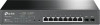
Smart PoE+ Switch 3. After the brackets are attached to the device, use suitable screws (not provided) to secure the brackets to the rack, as illustrated in the following figure. Rack Figure 2-3 Rack Installation Caution: ■■ Please set 5~10cm gaps around the device for air circulation. ■■ Please avoid any heavy thing placed on the device. ■■ Please mount devices in sequence from the bottom to top of the rack and ensure a certain clearance between devices for the purpose of heat dissipation. Installation 09
-
 1
1 -
2
-
3
-
4
-
5
-
6
-
7
-
8
-
9
-
 10
10 -
 11
11 -
 12
12 -
 13
13 -
 14
14 -
 15
15 -
 16
16 -
 17
17 -
 18
18 -
 19
19 -
 20
20 -
21
-
22
-
23
-
24
-
25
-
26
-
27
-
28
 |
 |

09
Smart PoE+ Switch
Installation
3. After the brackets are attached to the device, use suitable screws (not provided)
to secure the brackets to the rack, as illustrated in the following figure.
Rack
Figure 2-3 Rack Installation
Caution:
■
Please set 5~10cm gaps around the device for air circulation.
■
Please avoid any heavy thing placed on the device.
■
Please mount devices in sequence from the bottom to top of the rack and ensure
a certain clearance between devices for the purpose of heat dissipation.