TP-Link T1500G-10MPS T1500G-10MPSUN V1 Installation Guide - Page 10
Rear Panel
 |
View all TP-Link T1500G-10MPS manuals
Add to My Manuals
Save this manual to your list of manuals |
Page 10 highlights
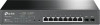
Smart PoE+ Switch ■■ Rear Panel The rear panel of T1500G-10MPS is shown as the following figure. Kensington Security Slot Power Socket Grounding Terminal Figure 1-2 Rear Panel of T1500G-10MPS Kensington Security Slot Secure the lock (not provided) into the security slot to prevent the device from being stolen. Power Socket Connect the female connector of the power cord here, and the male connector to the AC (Alternating Current) power outlet. Please make sure the voltage of the power supply meets the requirement of the input voltage. Grounding Terminal The switch already comes with lightning protection mechanism. You can also ground the switch through the PE (Protecting Earth) cable of AC cord or with Ground Cable. For detailed information, please refer to Chapter 3 Lightning Protection. Caution: Please use the provided power cord. 04 Introduction
-
 1
1 -
2
-
3
-
4
-
 5
5 -
 6
6 -
 7
7 -
 8
8 -
 9
9 -
 10
10 -
 11
11 -
 12
12 -
 13
13 -
 14
14 -
 15
15 -
16
-
17
-
18
-
19
-
20
-
21
-
22
-
23
-
24
-
25
-
26
-
27
-
28
 |
 |
