TP-Link TL-SG108E TL-SG108E V1 User Guide Easy Smart Configuration Utility 191 - Page 37
Easy Smart Configuration Utility, QoS Basic, Bandwidth Control, Storm Control
 |
View all TP-Link TL-SG108E manuals
Add to My Manuals
Save this manual to your list of manuals |
Page 37 highlights
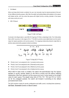
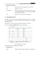
Easy Smart Configuration Utility User Guide 1. Port Based When port-base QoS mode is enabled, the user can manually map the ingress packets of the port to four different priority queues. After that, the switch will preferentially send packets in the queue with higher priority, and only when the queue with higher priority is empty, packets in the queue with lower priority are sent. 2. 802.1P Based Figure 7-2 802.1Q Frame As shown in the figure above, each 802.1Q Tag has a Pri field, comprising 3 bits. The 3-bit priority field is 802.1p priority in the range of 0 to 7. The 802.1p priority value determines how the switch maps the ingress packets to the priority queues. The mapping relationship between eight 802.1p priority value and priority queues is shown as follows: Figure 7-3 Map 802.1P Priority Priority 0 and 1 are assigned to the 1 (Lowest) priority queue. Priority 2 and 3 are assigned to the 2 (Normal) priority queue. Priority 4 and 5 are assigned to the 3 (Medium) priority queue. Priority 6 and 7 are assigned to the 4 (Highest) priority queue. When 802.1P QoS mode is enabled, the switch will automatically map the ingress packets to priority queues based on the 802.1p priority and the above mapping relationship. After that, packets in all the queues are sent in order based on the weight value for each queue. The weight value ratio of TC0, TC1, TC2 and TC3 is 1:2:4:8. As for the untagged packets, the switch will forward it according to the default port-based QoS mode. The QoS module is mainly for priority configuration and traffic control, including three submenus: QoS Basic, Bandwidth Control and Storm Control. 34
-
 1
1 -
2
-
3
-
4
-
5
-
6
-
7
-
8
-
9
-
10
-
11
-
12
-
13
-
14
-
15
-
16
-
17
-
18
-
19
-
20
-
21
-
22
-
23
-
24
-
25
-
26
-
27
-
28
-
29
-
30
-
31
-
 32
32 -
 33
33 -
 34
34 -
 35
35 -
 36
36 -
 37
37 -
 38
38 -
 39
39 -
 40
40 -
 41
41 -
 42
42
 |
 |
