Troy-Bilt Storm Tracker 2690 Operation Manual - Page 8
Top View
|
View all Troy-Bilt Storm Tracker 2690 manuals
Add to My Manuals
Save this manual to your list of manuals |
Page 8 highlights
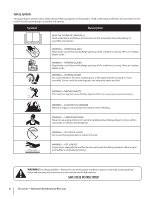
2. Insert chute control rod into chute control head. Push rod as far into chute control head as possible, keeping the holes in the rod pointing upward. See Fig. 3-4. 4. Squeeze the trigger on the joystick and rotate the chute by hand to face forward. The holes in the chute control input will be facing up. See Fig. 3-6. NOTE: The chute will not rotate without squeezing the trigger on the joystick. Chute Control Input Top View Figure 3-4 3. Place chute onto chute base and ensure chute control rod is positioned under the handle panel. Install hex bolt Figure 3-6 previously removed but do not secure with wing nut at this 5. Rotate the joystick to the one o'clock position so that the time. See Fig. 3-5. silver indicator arrow on the pinion gear below the control panel faces upward. See Fig. 3-7. NOTE: The joystick will be angled slightly to the right at the one o'clock position. See "Top View" in Fig. 3-6. Figure 3-5 8 Section 2- Assembly & Set-Up Figure 3-7
-
 1
1 -
2
-
 3
3 -
 4
4 -
 5
5 -
 6
6 -
 7
7 -
 8
8 -
 9
9 -
 10
10 -
 11
11 -
 12
12 -
 13
13 -
14
-
15
-
16
-
17
-
18
-
19
-
20
-
21
-
22
-
23
-
24
-
25
-
26
-
27
-
28
-
29
-
30
-
31
-
32
-
33
-
34
-
35
-
36
-
37
-
38
-
39
-
40
-
41
-
42
-
43
-
44
-
45
-
46
-
47
-
48
-
49
-
50
-
51
-
52
 |
 |
