Troy-Bilt TB32 Operation Manual
Troy-Bilt TB32 Manual
 |
View all Troy-Bilt TB32 manuals
Add to My Manuals
Save this manual to your list of manuals |
Troy-Bilt TB32 manual content summary:
- Troy-Bilt TB32 | Operation Manual - Page 1
Operator's Manual TB32 EC 2-Cycle Trimmer English - Page 1 Removing Unit From Carton Assemble The Unit 1 2 Remove all contents from the carton. Place shield onto mount bracket. Securely screw 2 shield screws through holes on mount bracket and into shield. Make sure screws - Troy-Bilt TB32 | Operation Manual - Page 2
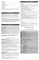
Service Information 2 Rules for Safe Operation 2 Know Your Unit 3 Assembly Instructions 3 Oil and Fuel Information 3 Starting and Stopping Instructions 4 Operating Instructions 4 Maintenance and Repair Instructions 4 Cleaning and Storage 5 Optional Accessory 5 Troubleshooting Chart - Troy-Bilt TB32 | Operation Manual - Page 3
• 3/8" Socket KNOW YOUR UNIT Spark Plug Muffler Choke Lever Starter Rope Grip On/Off Control Air Filter Cover Shaft Grip Throttle Control Fuel Cap Coupler D-Handle Shaft Housing Primer Bulb Line Cutting Blade Cutting Head Shield ASSEMBLY INSTRUCTIONS OPERATING THE COUPLER The coupler - Troy-Bilt TB32 | Operation Manual - Page 4
. 11). MAINTENANCE AND REPAIR INSTRUCTIONS MAINTENANCE SCHEDULE WARNING: To prevent serious injury, never perform maintenance or repairs with unit running. Always service and repair a cool unit. Disconnect the spark plug wire to ensure that the unit cannot start. Perform these required maintenance - Troy-Bilt TB32 | Operation Manual - Page 5
the carburetor adjusted by an authorized service dealer. MAINTAINING THE SPARK PLUG 1. Stop the engine and allow it to cool. Grasp the spark plug boot firmly and pull it from the spark plug. 2. Clean around the spark plug. Remove the spark plug from the cylinder head with a 5/8-inch socket, turning - Troy-Bilt TB32 | Operation Manual - Page 6
.troybilt.com or www.troybilt.ca Electric Start Feature Fig. 22 TROUBLESHOOTING CAUSE ENGINE WILL NOT START Empty fuel tank The primer bulb wasn't pressed enough Engine is flooded The fuel is old (over 30 days) and/or improperly mixed Fouled spark plug ACTION Fill fuel tank with properly mixed - Troy-Bilt TB32 | Operation Manual - Page 7
TB32 EC Recortador de 2 Ciclos Manual del Operador English - Page 1 Sacar la unidad de la vea la sección Cambiar la línea de corte de este manual. *Éste es asistir a la recarga de Splitline® solamente. Estas instrucciones no son parte de las instrucciones de asamblea rápidas. La línea no necesita - Troy-Bilt TB32 | Operation Manual - Page 8
manijas. • Mantenga las manos, la cara y los pies alejados de todas las partes en movimiento. No toque ni trate de parar el accesorio de corte cuando esté limpio, nuevo y sin plomo. • INDICADOR DE ACEITE Consulte el manual del operador para obtener información acerca del tipo correcto de aceite. - Troy-Bilt TB32 | Operation Manual - Page 9
combustible de mezcla o si su uso es inevitable, tome las precauciones recomendadas. • Use siempre una mezcla fresca de combustible según lo indica su manual del operador. • Use el aditivo especial de combustible STA-BIL® o uno similar • Agite siempre la mezcla de combustible antes de cargarlo en la - Troy-Bilt TB32 | Operation Manual - Page 10
DE ARRANQUE Y APAGADO INSTRUCTIONS DE DÉMARRAGE ADVERTENCIA parte trasera de la unidad. Consulte la sección de Operación del manual del operador del Arrancador Eléctrico o Accesorio de Arranque Eléctrico Opcional Power Start la unidad El accesorio de corte Bump Head™ le permite soltar línea de corte - Troy-Bilt TB32 | Operation Manual - Page 11
Enrolle el hilo ajustado en el sentido que se indica en la parte inferior del carrete interior hasta que queden aproximadamente 6 pulgadas (150 indica, el cabezal de corte funciona de manera incorrecta. Prosiga con la Parte 3 - Instalación del carretel interior. Divisor Ranura Ranuras de retención - Troy-Bilt TB32 | Operation Manual - Page 12
ño para limpiar la parte exterior de la unidad un accesorio de arranque Power Start Bit™, los cuales se - 11 libras (4.5 - 5 kg) Mecanismo de corte Bump Head™ Diámetro de la línea de corte 0.095 pulg (2. manual se basan en la información más reciente disponible en el momento de impresión del manual - Troy-Bilt TB32 | Operation Manual - Page 13
NOTES 13 - Troy-Bilt TB32 | Operation Manual - Page 14
NOTES 14 - Troy-Bilt TB32 | Operation Manual - Page 15
NOTES 15 - Troy-Bilt TB32 | Operation Manual - Page 16
returned directly to the factory will be accepted unless prior written permission has been extended by the Customer Service Department of Troy-Bilt. This limited warranty does not provide coverage in the following cases: A. Tune-ups - Spark Plugs, Carburetor Adjustments, Filters B. Wear items
-
 1
1 -
 2
2 -
 3
3 -
 4
4 -
 5
5 -
 6
6 -
 7
7 -
8
-
9
-
10
-
11
-
12
-
13
-
14
-
15
-
16
 |
 |
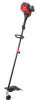
IMPORTANT: READ THE OPERATOR’S MANUAL THOROUGHLY AND FOLLOW THE SAFE OPERATION PRACTICES WHILE OPERATING THE UNIT.
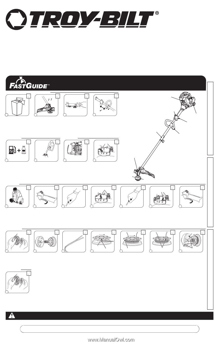
Bump
Knob
Inner
Reel
Outer
Spool
Spring
Top Hole
Bottom Hole
Split Wall
Unscrew the bump knob
counterclockwise.
Remove the inner reel and
spring.
Cut one 6-foot (1.8 m) length
of new 0.095” split line
trimming line. Split each end
about 6 inches (150 mm).
Insert the end of one line into
the top hole and the end of
the other line into the bottom
hole.
Wind the line tightly in the
direction shown on the inner
reel. The split wall will divide
the line. Wind the line until it
is completely divided and
about 6 inches (150 mm) of
line remains.
Insert the two 6-inch sections
into the two .095 holding
slots.
1
1
2
Pass the two line ends
through the eyelets. Place the
spring inside the inner reel.
Insert the inner reel into the
outer spool. Push the inner
reel and outer spool together.
Reloading the Line*
3
4
5
6
7
Hold the inner reel and outer
spool together. Firmly pull the
two line ends to release them
from the holding slots. Screw
the bump knob on clockwise.
Tighten the bump knob
securely.
1
8
For replacement line, call
1–800-828-5500
or go to
an authorized service dealer.
For
single line
installation or
replacement spool
installation instructions, refer to the
Replacing the
Trimming Line
section of this manual.
*This is to assist in the reloading of Splitline® only. These instructions
are NOT part of the fast assembly instructions. Line does not need to
be installed on the initial assembly and start-up.
Reloading the Line
Holding Slots
Eyelets
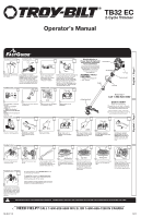
Removing Unit From Carton
Assemble The Unit
1
1
2
Remove all contents from
the carton.
Remove cap from lower
boom. Push cutting
attachment into coupler.
Turn coupler knob
clockwise to tighten.
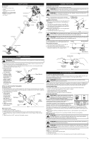
Crouch in starting position.
SQUEEZE
and
HOLD
throttle for
ALL
further
steps.
Pull
rope
5 times
.
Move
choke lever to
Position 2
and squeeze
throttle.
Pull
rope
3-5 times
to start
engine.
Run
unit for
30-60
seconds
to warm up.
Continue to squeeze
throttle.
Move
choke lever
to
Position 3
.
9
10
3
Continue to squeeze
throttle.
Run
unit for an
additional 60 seconds
to
complete warm-up. Unit
may be used during this
time.
Starting The Unit
11
12
13
14
15
5 X
3-5 X
Choke Lever
Choke Lever
Place
shield
onto
mount
bracket
. Securely screw
2
shield
screws
through holes on mount
bracket and into shield. Make
sure screws are tightened equally
so there is an equal gap between
bracket and shield on each side.
Starter Rope
Fuel Cap
Throttle Control
On/ Off Switch
D-Handle
Coupler
Cutting Head Shield
Need Help?
Call 1-800-828-5500
Electric Starter or
Power Start Bit Optional!
THESE OPTIONAL ACCESSORIES
ARE SOLD SEPARATELY!
This unit has an alternate starting method
that many find easier to use than pulling a
rope. Please contact a local retailer or call
1-800-828-5500
for more information.
Information may also be found at
www.troybilt.com
DIDN’T START?
Repeat these instructions.
IF
engine fails to start after 2 attempts,
move choke lever to position 3 and pull
the starter rope until engine starts
IF
unit still fails to start, refer to the
operator’s manual for additional starting
and troubleshooting information
ASSEMBLY TOOLS
REQUIRED:
•
Phillips #2 Screwdriver
•
3/8” Socket
Push the handle onto the shaft housing.
The bolt hole should be to the right.
Insert the bolt into the bolt hole.
Tighten the bolt, but not completely.
Move the handle to the location that
provides the best grip. Move the
handle a minimum of
6 inches
away
from the shaft grip. Tighten the bolt
until the handle is secure.
4
Min. 6”
Assemble The Unit
Starting The Unit
Mix thoroughly in separate
fuel can:
– 3.2 fl. oz. of 2-cycle
engine oil
– 1 gallon of unleaded
gasoline (less than 30 days
old)
NOTE:
Do not mix directly in
fuel tank.
Place unit on a level surface.
Fill fuel tank.
Press
primer bulb
10 times
,
or until fuel is visible
5
6
7
Move
choke lever to
Position 1
.
8
Primer
Bulb
10 X
1 Gallon
3.2 oz
40:1
Choke Lever
769-08427 / 00
09/12
Engli
s
h — Page 1
E
s
pañol — Page 7
NEED HELP
?
CALL 1-800-828-5500 IN U.
S
. OR 1–800–668–1238 IN CANADA
TB32 EC
2-Cycle Trimmer
Operator
’s
Manual