Uniden UM415 English Owners Manual - Page 33
Connec°ng the radio - vhf marine radio
 |
UPC - 050633501290
View all Uniden UM415 manuals
Add to My Manuals
Save this manual to your list of manuals |
Page 33 highlights
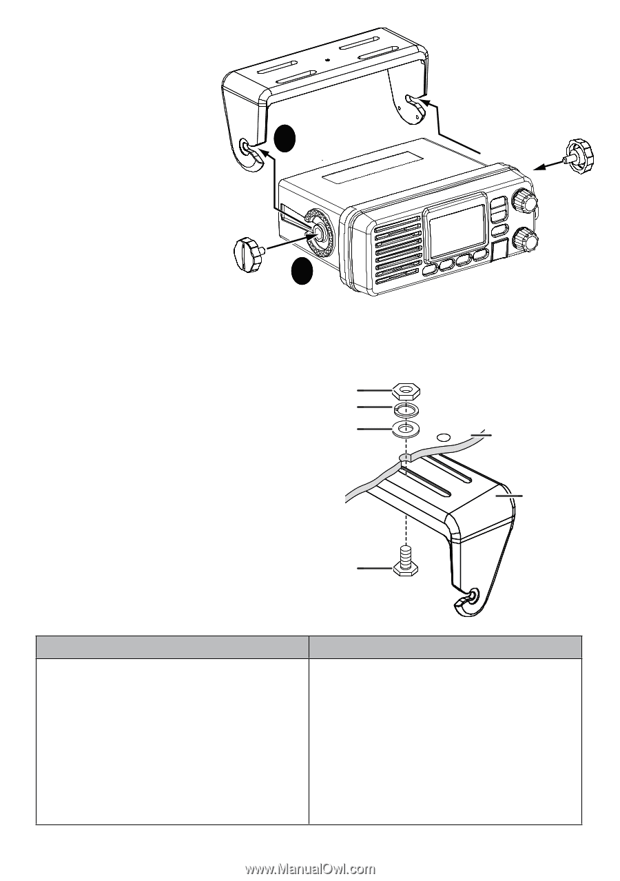
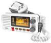
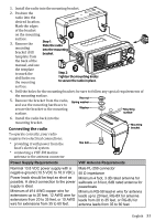
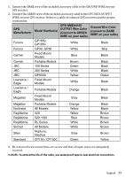
1. Install the radio into the mounting bracket. 2. Position the radio into the desired location. Mark the edges of the bracket on the mounting 1 surface. 3. Remove the Step 1: Slide the radio mounting into the mounting bracket drill bracket. template from the back of the manual, and use the template to mark the drill holes on the mounting 2 Step 2: Tighten the mounting knobs to secure the radio in place. surface. 4. Drill the holes for the mounting bracket; be sure to follow any special requirements of the mounting surface. 5. Remove the bracket from the radio, and use the mounting hardware to secure the bracket to the mounting Hex nut Spring washer Washer Mounting surface. surface 6. Install the radio back into the mounting bracket. Connecting the radio Mounting bracket To operate correctly, your radio requires two electrical connections: providing it with power from the boat's electrical system Hex bolt connecting a VHF-FM marine antenna to the antenna connector Power Supply Requirements VHF Antenna Requirements Nominal 13.8 VDC power supply with a Male PL-259 connector negative ground (10.5 VDC to 16.0 VDC). 50 Ω impedance Power leads should be kept as short as Minimum 4 foot, 3 dB rated antenna for possible. A direct connection to the power sailboats or 8 foot, 6dB rated antenna for supply is ideal. powerboats Minimum of #14 AWG copper wire for Minimum RG-58 lead-in wire for antenna extensions up to 20 feet, 12 AWG wire for leads up to 20 feet, RG-8X for antenna extensions from 20 to 35 feet, or 10 AWG leads from 20 to 35 feet, or RG-8U for wire for extensions from 35 to 60 feet. antenna leads from 35 to 60 feet. English 33
-
 1
1 -
2
-
3
-
4
-
5
-
6
-
7
-
8
-
9
-
10
-
11
-
12
-
13
-
14
-
15
-
16
-
17
-
18
-
19
-
20
-
21
-
22
-
23
-
24
-
25
-
26
-
27
-
 28
28 -
 29
29 -
 30
30 -
 31
31 -
 32
32 -
 33
33 -
 34
34 -
 35
35 -
 36
36 -
 37
37 -
 38
38 -
39
-
40
-
41
-
42
-
43
-
44
-
45
-
46
-
47
-
48
-
49
-
50
-
51
-
52
-
53
 |
 |