Uniden UM415 English Owners Manual - Page 34
Connec°ng to a GPS receiver - black
 |
UPC - 050633501290
View all Uniden UM415 manuals
Add to My Manuals
Save this manual to your list of manuals |
Page 34 highlights
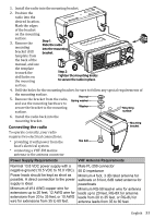
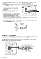
1. Connect the BLACK wire of the power cable to the NEGATIVE (-) side of your power source. 2. Connect the RED wire of the power cable to the POSITIVE (+) side of your power source. 3. NOTE: To extend the life of the radio, Red wire (+) use waterproof tape to seal electrical connections. 4. Install your antenna according to the manufacturer's instructions. 5. If necessary, consult the FCC guidelines for antenna separation. See Antenna Selection and Installation on page 51 for more 13.8V DC Black wire (-) details. (In summary, the FCC recommends that antennas up to 3 dB be installed a minimum of 3 feet from any occupied location; antennas over 3 dB should be installed at least 6 feet away.) 6. Connect the PL-259 connector from the antenna lead-in wires to the SO238 connector labeled ANTENNA on the back of your radio. Radio connector, SO238 (female PL-259) Antenna lead-in connector, male PL-259 Connecting to a GPS receiver If you connect the radio to a GPS receiver, the radio can automatically transmit your current position during an automated distress call or during a normal DSC call. Your radio supports a standard NMEA0183 input from a GPS receiver. Follow the steps below to connect your radio to your GPS receiver: 13.8V DC Orange: NMEA OUT (-) Black: Ext. Speaker (-)/GND Green: GPS Data IN (+) Red: External Speaker (+) Bare wire: Ground Yellow: NMEA OUT (+) 34 English
-
 1
1 -
2
-
3
-
4
-
5
-
6
-
7
-
8
-
9
-
10
-
11
-
12
-
13
-
14
-
15
-
16
-
17
-
18
-
19
-
20
-
21
-
22
-
23
-
24
-
25
-
26
-
27
-
28
-
 29
29 -
 30
30 -
 31
31 -
 32
32 -
 33
33 -
 34
34 -
 35
35 -
 36
36 -
 37
37 -
 38
38 -
 39
39 -
40
-
41
-
42
-
43
-
44
-
45
-
46
-
47
-
48
-
49
-
50
-
51
-
52
-
53
 |
 |
