Via 7001G User Manual
Via 7001G - VIA Mini ITX Motherboard Manual
 |
UPC - 825529000788
View all Via 7001G manuals
Add to My Manuals
Save this manual to your list of manuals |
Via 7001G manual content summary:
- Via 7001G | User Manual - Page 1
User's Manual VB7001 Version 1.13 January 18, 2012 - Via 7001G | User Manual - Page 2
mechanical, magnetic, optical, chemical, manual or otherwise without the prior written permission of VIA Technologies, Incorporated. Trademarks All trademarks are if not installed and used in accordance with the instruction manual, may cause harmful interference to radio communications. Operation - Via 7001G | User Manual - Page 3
1. Always read the safety instructions carefully. 2. Keep this User's Manual for future reference. 3. Keep this equipment away from . 11. If any of the following situations arises, get the equipment checked by a service personnel: • The power cord or plug is damaged • Liquid has penetrated into the - Via 7001G | User Manual - Page 4
- Via 7001G | User Manual - Page 5
BOX CONTENTS One VIA Mini-ITX mainboard One Quick Installation Guide One ATA-133/100 IDE ribbon cable One driver and utilities CD One IO bracket i - Via 7001G | User Manual - Page 6
TABLE OF CONTENTS Box Contents i Table of Contents ii Chapter 1 1 Specifications 1 Mainboard Specifications 2 Mainboard Layout 4 Back Panel Layout 5 Chapter 2 7 Installation 7 CPU 8 Memory Module Installation 10 Connecting the Power Supply 11 Back Panel Ports 12 Connectors 14 Jumpers - Via 7001G | User Manual - Page 7
Power Management Setup 45 Peripheral Activities 47 IRQs Activities 50 PNP/PCI Configurations 51 IRQ Resources 53 Frequency / Voltage Control 54 Load Fail-Safe Defaults 58 Load Optimized Defaults 59 Set Supervisor / User Password 60 Save & Exit Setup 62 Exit Without Saving 63 Chapter 4 65 - Via 7001G | User Manual - Page 8
This page is left intentionally blank. iv - Via 7001G | User Manual - Page 9
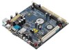
CHAPTER 1 Specifications The ultra-compact and highly integrated VIA VB7001 uses the Mini-ITX mainboard form-factor developed by VIA Technologies, Inc. as part of the company's open industry-wide total connectivity initiative. The mainboard enables the creation of an exciting new generation of small - Via 7001G | User Manual - Page 10
Chapter 1 MAINBOARD SPECIFICATIONS CPU • VIA C7®-D 1.5GHz NanoBGA2 Processor Chipset • VIA CN700 North Bridge • VIA VT8237R Plus South Bridge Graphics • Integrated UniChrome™ Pro AGP with MPEG-2 Acceleration Audio • VIA VT1618 AC'97 Codec Memory • 1 x DDR2 533 DIMM slot (up to 1 GB) Expansion Slot • - Via 7001G | User Manual - Page 11
S/PDIF • 1 x S-Video port (optional) BIOS • Award BIOS with LPC 4Mbit flash memory capacity Form Factor • Mini-ITX (4 layers) • 17cm X 17cm Note: Due to the hardware limitation, DDR2 SDRAM chips organized as 128Mb x 8 bank cannot be supported by EPIA products with CN700 and CX700M chipsets. 3 - Via 7001G | User Manual - Page 12
Chapter 1 MAINBOARD LAYOUT 4 - Via 7001G | User Manual - Page 13
BACK PANEL LAYOUT Specifications 5 - Via 7001G | User Manual - Page 14
This page is left intentionally blank. 6 - Via 7001G | User Manual - Page 15
CHAPTER 2 Installation This chapter provides you with information about hardware installation procedures. It is recommended to use a grounded wrist strap before handling computer components. Electrostatic discharge (ESD) can damage some components. 7 - Via 7001G | User Manual - Page 16
Chapter 3 CPU The VIA VB7001 Mini-ITX mainboard includes an embedded VIA C7-D V4 Bus Processor. The VIA C7-D V4 Bus Processor requires a heatsink with a fan to provide sufficient cooling. 8 - Via 7001G | User Manual - Page 17
BIOS Setup CPU Fan and System Fan: CPUFAN and SYSFAN The CPUFAN (CPU fan) and SYSFAN (system fan) run on +12V and maintain system cooling. When connecting the wire to the connectors, always be aware that the red wire is the Positive and should be connected to the +12V. The black wire is Ground and - Via 7001G | User Manual - Page 18
Chapter 3 MEMORY MODULE INSTALLATION The VIA VB7001 Mini-ITX mainboard provides one 240-pin DIMM slot for DDR2 533 SDRAM memory modules and supports the memory size up to 1GB. DIMM DDR SDRAM Module Installation Procedures • Locate the DIMM slot in the motherboard. • Unlock a DIMM slot by pressing - Via 7001G | User Manual - Page 19
BIOS Setup CONNECTING THE POWER SUPPLY The VIA VB7001 Mini-ITX mainboard supports a conventional ATX power supply for the power system. Good 9 +5V Standby 10 +12V 11 +3.3V 12 -12V 13 GND 14 Power Supply On 15 GND 16 GND 17 GND 18 NC 19 +5V 20 +5V ATXPWR 11 1 20 10 11 - Via 7001G | User Manual - Page 20
Chapter 3 BACK PANEL PORTS The back panel has the following ports: Mouse and Keyboard The connector above is for a PS/2 mouse, and the one below is for a PS/2 keyboard. RCA / SPDIF Jack The RCA jack connects to external composite video device or audio output device. S-Video Port The black port - Via 7001G | User Manual - Page 21
Serial port: COM The 9-pin COM port is for pointing devices or other serial devices. BIOS Setup VGA Port The 15-pin female VGA connector can be used to connect to any analog VGA monitor. RJ45 10/100 LAN and USB Connector The mainboard provides a standard RJ-45 and USB 2.0 ports. These ports allow - Via 7001G | User Manual - Page 22
Chapter 3 CONNECTORS Hard Disk Connectors: IDE1 & IDE2 The mainboard has a 32-bit Enhanced IDE and Ultra DMA 133/100/66 controller that provides PIO mode 0~4, Bus Master, and Ultra DMA 133/100/66 functions. You can connect up to four hard disk drives, CD-ROM and other devices. The primary hard drive - Via 7001G | User Manual - Page 23
5 -PLED_2 7 +5V 9 NC 11 NC 13 SPEAK 15 Key Pin Signal 2 +5V 4 HD_LED 6 PW_BN 8 GND 10 RST_SW 12 GND 14 +5V 16 -SLEEP_LED 1 2 15 16 Power Switch (PW_BN) Connect to a 2-pin power button switch. Pressing this button will turn the system power on or off. Reset Switch - Via 7001G | User Manual - Page 24
Chapter 3 Serial ATA Connectors: SATA1 and SATA2 These next generation connectors support the thin Serial ATA cables for primary internal storage devices. The current Serial ATA interface host and/or other SMBus devices using the SMBus interface. Pin Signal 1 SMBCK 2 SMBDT 3 GND SMBUS 1 16 - Via 7001G | User Manual - Page 25
BIOS Setup USB Pin Connectors: USB 0-1 and USB 2-3 The mainboard provides 2 USB pin headers, allowing up to 4 additional USB2.0 ports up to maximum throughput of 480 Mbps. Connect each 2-port USB cable into this pin header. This port can be used to connect high-speed USB interface peripherals - Via 7001G | User Manual - Page 26
Chapter 3 Front Panel Audio Connector: F_AUDIO This is an interface for the VIA front panel audio cable that allow convenient connection and control of audio devices. By default, the pins labeled LINE_OUT_R/NEXT_R and the pins LINE_OUT_L/NEXT_L - Via 7001G | User Manual - Page 27
BIOS Setup JUMPERS The mainboard provides jumpers for setting some mainboard functions. This section will explain how to change the settings of the mainboard functions using the jumpers. Clear CMOS: CLEAR_CMOS The onboard CMOS RAM stores system configuration data and has an onboard battery power - Via 7001G | User Manual - Page 28
Chapter 3 SLOTS Peripheral Component Interconnect: PCI The PCI slot allows you to insert PCI expansion card. When adding or removing expansion card, unplug first the power supply. Read the documentation for the expansion card if any changes to the system are necessary. PCI PCI Interrupt Request - Via 7001G | User Manual - Page 29
CHAPTER 3 BIOS Setup This chapter gives a detailed explanation of the BIOS setup functions. 21 - Via 7001G | User Manual - Page 30
Chapter 3 ENTERING SETUP Power on the computer and press during the beginning of the boot sequence to enter the BIOS setup menu. If you missed the BIOS setup entry point, you may restart the system and try again. 22 - Via 7001G | User Manual - Page 31
CONTROL KEYS Keys Up Arrow Down Arrow Left Arrow Right Arrow Enter Escape Page Up / + Page Down / F1 F5 F6 F7 F9 F10 BIOS Setup Description Move to the previous item Move to the next item Move to the item in the left side Move to the item in the right side Select the item Jumps to the Exit menu or - Via 7001G | User Manual - Page 32
Chapter 3 NAVIGATING THE BIOS MENUS The main menu displays all the BIOS setup categories. Use the control keys Up/Down arrow keys to select any item/sub-menu. Description of the selected/highlighted category is displayed at the bottom of the screen. An arrow symbol next to a field indicates that a - Via 7001G | User Manual - Page 33
BIOS Setup GETTING HELP The BIOS setup program provides a "General Help" screen. You can display this screen from any menu/sub-menu by pressing . The help screen displays the keys for using and navigating the BIOS setup. Press to exit the help screen. 25 - Via 7001G | User Manual - Page 34
Chapter 3 MAIN MENU Phoenix - AwardBIOS CMOS Setup Utility Standard CMOS Features Advanced BIOS Features Advanced Chipset Features Integrated Peripherals Power Management Setup PnP / PCI Configurations Frequency / Voltage Control Load Fail-Safe Defaults Load Optimized Defaults Set Supervisor - Via 7001G | User Manual - Page 35
BIOS Setup Load Fail-Safe Defaults Use this menu option to load the BIOS default settings for minimal and stable system operations. Load Optimized Defaults Use this menu option to load BIOS default settings for optimal and high performance system operations. Set Supervisor Password Use this menu - Via 7001G | User Manual - Page 36
, year and century Halt On Base Memory Extended Memory Total Memory [All , But Keyboard] 640K 15360K 16384K : Move Enter: Select F5: Previous Values +/-/PU/PD: Value F10: Save F6: Fail-Safe Defaults ESC: Exit F1: General F7: Optimized Defaults Help Date The date format is [Day, Month, Date - Via 7001G | User Manual - Page 37
0 0 0 0 [Auto] [Auto] : Move Enter: Select F5: Previous Values +/-/PU/PD: Value F10: Save F6: Fail-Safe Defaults ESC: Exit F1: General F7: Optimized Defaults Help this category. Select "Auto" whenever possible. If you select "Manual", make sure the information is from your hard disk vendor or - Via 7001G | User Manual - Page 38
[CDROM] [Hard Disk] [Enabled] [On] [Disabled] 6 250 [Setup] [Enabled] [1.4] [Enabled] [Disabled] Item Help Menu Level : Move Enter: Select F5: Previous Values +/-/PU/PD: Value F10: Save F6: Fail-Safe Defaults ESC: Exit F1: General F7: Optimized Defaults Help Virus Warning This item is used to - Via 7001G | User Manual - Page 39
BIOS Setup First/Second/Third Boot Device Set the boot device sequence as BIOS attempts to load the disk operating system. Setting LS120 Hard Disk CD-ROM ZIP100 USB-FDD USB-ZIP USB-CDROM Legacy LAN Disabled Description Boot from LS-120 drive Boot from the HDD Boot from CD-ROM Boot from ATAPI ZIP - Via 7001G | User Manual - Page 40
Chapter 3 Typematic Rate (Chars/Sec) This item sets the rate (characters/second) at which the system retrieves a signal from a depressed key. Settings: [6, 8, 10, 12, 15, 20, 24, 30] Typematic Delay (Msec) This item sets the delay between when the key was first pressed and when the system begins to - Via 7001G | User Manual - Page 41
] [Disabled] Item Help Menu L evel Thermal Monitor 1 (O n die throtting) Thermal Monitor 2 (Ratio & VID transition) : Move Enter: Select F 5: Previous Values +/-/PU/PD: Value F10: Save F6: Fail- Safe Defaults ESC: Exit F1: General F7: Optimized Defau lts Help Thermal Management To set CPU - Via 7001G | User Manual - Page 42
Chapter 3 TM2 Bus VID To set the voltage of the throttled performance that will be initiated when the on die sensor goes from not hot to hot. Settings: [0.700V, 0.716V, 0.732V, 0.748V, 0.764V, 0.780V, 0.796V, 0.812V, 0.828V, 0.844V, 0.860V, 0.876V, 0.892V, 0.908V, 0.924V, 0.940V, 0.956V, 0.972V, 0. - Via 7001G | User Manual - Page 43
move it up, or < - > to move it down the list. Press to exit this menu. BIOS Setup : Move Enter: Select F5: Previous Values +/-/PU/PD: Value F10: Save F6: Fail-Safe Defaults ESC: Exit F1: General F7: Optimized Defaults Help This is for setting the priority of the hard disk - Via 7001G | User Manual - Page 44
which one to boot : Move Enter: Select F5: Previous Values +/-/PU/PD: Value F10: Save F6: Fail-Safe Defaults ESC: Exit F1: General F7: auto or manual. Always fix this setting to optimized default value unless you have problems with special video cards Settings: [Auto, Manual] Select Display - Via 7001G | User Manual - Page 45
Panel Type Key in a HEX number. Settings: [Min = 0000, Max = 000F] BIOS Setup TV H/W Layout Settings: [COMPOSITE + S-Video, COMPOSITE, S-Video] TV Type This setting refers to the native resolution of the display being used with the system. Settings: [NTSC, PAL] 37 - Via 7001G | User Manual - Page 46
[Enabled] Item Help Menu Level : Move Enter: Select F5: Previous Values +/-/PU/PD: Value F10: Save F6: Fail-Safe Defaults ESC: Exit F1: General F7: : [32MB, 64MB, 128MB, 256MB, 512MB, 1G] AGP 2.0 Mode This mainboard supports the AGP 4x interface. When the AGP 4x video card is used, it can - Via 7001G | User Manual - Page 47
AGP 3.0 Calibration Cycle Settings: [Enabled, Disabled] VGA Share Memory Size Settings: [Disabled, 16M, 32M, 64M] Direct Frame Buffer Settings: [Enabled, Disabled] BIOS Setup 39 - Via 7001G | User Manual - Page 48
Chapter 3 CPU & PCI BUS CONTROL VLink mode selection VLink 8X Support DRDY_Timing Phoenix - AwardBIOS CMOS Setup Utility CPU & PCI Bus Control [By Auto] [Enabled] [Default] Item Help Menu Level : Move Enter: Select F5: Previous Values +/-/PU/PD: Value F10: Save F6: Fail-Safe Defaults ESC: Exit - Via 7001G | User Manual - Page 49
CMOS Setup Utility TV Output Connector [Enabled] [Enabled] Item Help Menu Level BIOS Setup : Move Enter: Select F5: Previous Values +/-/PU/PD: Value F10: Save F6: Fail-Safe Defaults ESC: Exit F1: General F7: Optimized Defaults Help CVBS (Composite) Settings: [Enabled, Disabled] S-Video - Via 7001G | User Manual - Page 50
Enabled] [Enabled] [On] : Move Enter: Select F5: Previous Values +/-/PU/PD: Value F10: Save F6: Fail-Safe Defaults ESC: Exit F1: General F7: 2 The integrated peripheral controller contains an IDE interface with support for two IDE channels. Setting Enabled Disabled Description Activates - Via 7001G | User Manual - Page 51
two SATA plus two PATA hard disk drives Only SATA supports RAID AC'97 Audio Auto allows the mainboard to detect whether an audio device is used. If the device is detected, the onboard VIA AC'97 (Audio Codec'97) controller will be enabled; otherwise, it is disabled. Disable the controller if - Via 7001G | User Manual - Page 52
DMA Phoenix - AwardBIOS CMOS Setup Utility SuperIO Device [3F8/IRQ4] [Disabled] 3 6 Item Help Menu Level : Move Enter: Select F5: Previous Values +/-/PU/PD: Value F10: Save F6: Fail-Safe Defaults ESC: Exit F1: General F7: Optimized Defaults Help Onboard Serial Port 1 To set the base I/O port - Via 7001G | User Manual - Page 53
[Suspend -> Off] Power Off by PWRBTN Run VGABIOS if S3 Resume AC Loss Auto Restart Peripherals Activities IRQs Activities [Instant-Off] [Auto] [ OS to select S1 or S3 : Move Enter: Select F5: Previous Values +/-/PU/PD: Value F10: Save F6: Fail-Safe Defaults ESC: Exit F1: General F7: Optimized - Via 7001G | User Manual - Page 54
BIOS if resuming from S3 state. necessary for older VGA drivers. This is only Settings: [Auto, Yes, No] AC Loss Auto restart The field defines how the system will respond after an AC power loss during system operation. Setting Off On Former-Sts Description Keeps the system in an off state until - Via 7001G | User Manual - Page 55
Help Menu Level When Select Password, Please press ENTER key to change Password Max 8 numbers. : Move Enter: Select F5: Previous Values +/-/PU/PD: Value F10: Save F6: Fail-Safe Defaults ESC: Exit F1: General F7: Optimized Defaults Help PS2KB Wakeup Select When selecting "Password", press - Via 7001G | User Manual - Page 56
Chapter 3 USB Resume from S3 Enables activity detected from USB devices to restore the system from a suspended state to an active state. Settings: [Disabled, Enabled] VGA Event Enables the power management unit to monitor VGA activities. Settings: [Off, On] COM Event Decide whether or not the power - Via 7001G | User Manual - Page 57
BIOS Setup RTC Alarm Resume Sets a scheduled time and/or date to automatically power on the system. Settings: [Disabled, Enabled] Date (of Month) The field specifies the date for "RTC Alarm Resume". Resume Time (hh:mm:ss) The field specifies the time for "RTC Alarm Resume". 49 - Via 7001G | User Manual - Page 58
power management unit will not monitor any IRQ activities. : Move Enter: Select F5: Previous Values +/-/PU/PD: Value F10: Save F6: Fail-Safe Defaults ESC: Exit F1: General F7: Optimized Defaults Help ready, the system will interrupt itself and perform the service required by the IO device. 50 - Via 7001G | User Manual - Page 59
and Play capable operating system. Select No if you need the BIOS to configure non-boot devices : Move Enter: Select F5: Previous Values +/-/PU/PD: Value F10: Save F6: Fail-Safe Defaults ESC: Exit F1: General F7: Optimized Defaults Help Note: This section covers some very technical items and - Via 7001G | User Manual - Page 60
to automatically configure all the Plug-and-Play compatible devices. Setting Auto(ESCD) Manual Description BIOS will automatically assign IRQ, DMA and memory base address fields Unlocks "IRQ Resources" for manual configuration Assign IRQ For VGA/USB Assign IRQ for VGA and USB devices. Settings - Via 7001G | User Manual - Page 61
or ISA bus architecture : Move Enter: Select F5: Previous Values +/-/PU/PD: Value F10: Save F6: Fail-Safe Defaults ESC: Exit F1: General Note: The items are adjustable only when "Resources Controlled By" is set to "Manual." IRQ Resources list IRQ 3/4/5/7/9/10/11/12/14/15 for users to set each - Via 7001G | User Manual - Page 62
+/-/PU/PD: Value F10: Save F6: Fail-Safe Defaults ESC: Exit F1: General F7: Optimized Defaults Help DRAM Clock The chipset supports synchronous and memory that has a different performance rating than the original modules. Settings: [Manual, Auto By SPD, Turbo, Ultra] SDRAM CAS Latency [DDR/DDR2] - Via 7001G | User Manual - Page 63
This improves performance of the SDRAM by masking the refresh time of each bank. This field is only available when "DRAM Timing" is set to "Manual". Settings: [Disabled, 2 Bank, 4 Bank, 8 Bank] Precharge to Active (Trp) This field is for setting the length of time it takes to precharge a row in the - Via 7001G | User Manual - Page 64
faster command rate. Note: Some memory modules may not be able to handle lower settings. Settings: [2T Command, 1T Command] RDSAIT Mode Settings: [Manual, Auto] RDSAIT Selection Key in a HEX number. Settings: [Min = 0000, Max = 003F] Auto Detect PCI Clk Settings: [Disabled, Enabled] CPU Clock Key in - Via 7001G | User Manual - Page 65
CPU Clock Ratio This field is for setting the CPU internal clock multiplier. BIOS Setup Note: This option does NOT apply to CPU(S) which have this clock multiplier LOCKED!! Key in a DEC number. Settings: [Min = 4, Max = 50] Spread Spectrum When the mainboard's clock generator pulses, the extreme - Via 7001G | User Manual - Page 66
Chapter 3 LOAD FAIL-SAFE DEFAULTS Phoenix - AwardBIOS CMOS Setup Utility Standard CMOS Features Advanced BIOS Features Advanced Chipset Features Integrated Peripherals Power Management Setup PnP / PCI Configurations Frequency / Voltage Control Load Fail-Safe Defaults Load Optimized Defaults Set - Via 7001G | User Manual - Page 67
LOAD OPTIMIZED DEFAULTS Phoenix - AwardBIOS CMOS Setup Utility Standard CMOS Features Load Fail-Safe Defaults Advanced BIOS Features Load Optimized Defaults Advanced Chipset Features Set Supervisor Password Integrated Peripherals Set User Password Power Management Setup Save & Exit Setup - Via 7001G | User Manual - Page 68
Chapter 3 SET SUPERVISOR / USER PASSWORD Phoenix - AwardBIOS CMOS Setup Utility Standard CMOS Features Advanced BIOS Features Advanced Chipset Features Integrated Peripherals Power Management Setup PnP / PCI Configurations Enter Password: Frequency / Voltage Control Load Fail-Safe Defaults Load - Via 7001G | User Manual - Page 69
BIOS Setup Additionally, when a password is enabled, the BIOS can be set to request the password each time the system is booted. This would prevent unauthorized use of the system. See "Security Option" in the "Advanced BIOS Features" section for more details. 61 - Via 7001G | User Manual - Page 70
Chapter 3 SAVE & EXIT SETUP Phoenix - AwardBIOS CMOS Setup Utility Standard CMOS Features Advanced BIOS Features Advanced Chipset Features Integrated Peripherals Power Management Setup PnP / PCI Configurations Frequency / Voltage Control Load Fail-Safe Defaults Load Optimized Defaults Set - Via 7001G | User Manual - Page 71
EXIT WITHOUT SAVING Phoenix - AwardBIOS CMOS Setup Utility Standard CMOS Features Advanced BIOS Features Advanced Chipset Features Integrated Peripherals Power Management Setup PnP / PCI Configurations Frequency / Voltage Control Load Fail-Safe Defaults Load Optimized Defaults Set Supervisor - Via 7001G | User Manual - Page 72
Chapter 3 64 - Via 7001G | User Manual - Page 73
CHAPTER 4 Driver Installation This chapter gives you brief descriptions of each mainboard driver and application. You must install the VIA chipset drivers first before installing other drivers such as audio or VGA drivers. The applications will only function correctly if the necessary drivers are - Via 7001G | User Manual - Page 74
Chapter 4 DRIVER UTILITIES Getting Started The Driver Utilities CD contains the driver utilities and software for enhancing the performance of the mainboard. Note: The driver utilities and software are updated from time to time. The latest updated versions are available at http://www.viaembedded.com - Via 7001G | User Manual - Page 75
Driver Installation Running the Driver Utilities CD To start using the CD, insert the CD into the CD-ROM or DVD-ROM drive. The CD should run automatically after closing the CD-ROM or DVD-ROM drive. The driver utilities and software menu screen should then appear on the screen. If the CD does not run - Via 7001G | User Manual - Page 76
Chapter 4 CD CONTENT VIA 4in1 Drivers: Contains VIA ATAPI Vendor Support Driver (enables the performance enhancing bus mastering functions on ATA-capable Hard Disk Drives and ensures IDE device compatibility), AGP VxD Driver (provides service routines to your VGA driver and interface directly to
-
 1
1 -
 2
2 -
 3
3 -
 4
4 -
 5
5 -
 6
6 -
 7
7 -
8
-
9
-
10
-
11
-
12
-
13
-
14
-
15
-
16
-
17
-
18
-
19
-
20
-
21
-
22
-
23
-
24
-
25
-
26
-
27
-
28
-
29
-
30
-
31
-
32
-
33
-
34
-
35
-
36
-
37
-
38
-
39
-
40
-
41
-
42
-
43
-
44
-
45
-
46
-
47
-
48
-
49
-
50
-
51
-
52
-
53
-
54
-
55
-
56
-
57
-
58
-
59
-
60
-
61
-
62
-
63
-
64
-
65
-
66
-
67
-
68
-
69
-
70
-
71
-
72
-
73
-
74
-
75
-
76
 |
 |

User’s Manual
VB7001
Version 1.13
January 18, 2012