Via EPIA-EK10000G User Manual
Via EPIA-EK10000G - VIA Motherboard - Mini ITX Manual
 |
UPC - 825529003581
View all Via EPIA-EK10000G manuals
Add to My Manuals
Save this manual to your list of manuals |
Via EPIA-EK10000G manual content summary:
- Via EPIA-EK10000G | User Manual - Page 1
User's Manual EPIA-EK Version 1.32 March 9, 2012 - Via EPIA-EK10000G | User Manual - Page 2
into any language, in any form or by any means, electronic, mechanical, magnetic, optical, chemical, manual or otherwise without the prior written permission of VIA Technologies, Incorporated. Trademarks All trademarks are the property of their respective holders. PS/2 is a registered trademark of - Via EPIA-EK10000G | User Manual - Page 3
. This equipment generates, uses and can radiate radio frequency energy and, if not installed and used in accordance with the instruction manual, may cause harmful interference to radio communications. Operation of this equipment in a residential area is likely to cause harmful interference - Via EPIA-EK10000G | User Manual - Page 4
1. Always read the safety instructions carefully. 2. Keep this User's Manual for future reference. 3. Keep this equipment away from . 11. If any of the following situations arises, get the equipment checked by a service personnel: • The power cord or plug is damaged • Liquid has penetrated into the - Via EPIA-EK10000G | User Manual - Page 5
BOX CONTENTS One VIA Mini-ITX mainboard One Quick Installation Guide One ATA-133/100/66 IDE ribbon cable One driver and utilities CD One IO bracket i - Via EPIA-EK10000G | User Manual - Page 6
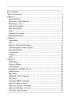
Mainboard Specifications 2 Mainboard Layout 4 Back Panel Layout 5 Back Panel Ports 6 Slots 6 Onboard Connectors 7 Onboard Jumpers 7 Chapter 2 8 Installation 8 CPU 9 Memory 36 Hard Disk Boot Priority 39 Advanced Chipset Features 40 AGP & P2P Bridge Control 42 CPU & PCI Bus Control 43 ii - Via EPIA-EK10000G | User Manual - Page 7
59 Load Fail-Safe Defaults 62 Load Optimized Defaults 63 Set Supervisor / User Password 64 Save & Exit Setup 66 Exit Without Saving 67 Chapter 4 68 Driver Installation 68 Driver Utilities 69 CD Content 71 iii - Via EPIA-EK10000G | User Manual - Page 8
This page is left intentionally blank. iv - Via EPIA-EK10000G | User Manual - Page 9
CHAPTER 1 Specifications The ultra-compact and highly integrated VIA EPIA-EK uses the Mini-ITX mainboard form-factor developed by VIA Technologies, Inc. as part of the company's open industry-wide Total Connectivity initiative. The mainboard enables the creation of an exciting new generation of - Via EPIA-EK10000G | User Manual - Page 10
Chapter 1 MAINBOARD SPECIFICATIONS CPU • VIA Luke CoreFusion™ Processor Chipset • VIA VT8237R-series South Bridge Graphics • Integrated UniChrome™ Pro AGP with MPEG-2 Acceleration Audio • VIA VT1618 AC'97 Codec with 6-channel support Memory • 1 x DDR 400 DIMM slot (up to 1 GB) Expansion Slot • - Via EPIA-EK10000G | User Manual - Page 11
2.0 ports • 3 x Audio Jacks: line-out, line-in and mic-in (Vertical, Smart 5.1 Support) Onboard I/O Connectors • 2 x USB pin headers for 4 USB 2.0 ports • 1 x SIR pin Award BIOS with 2/4/8Mbit flash memory capacity ACPI1.0b, SMBIOS2.3 and DMI2.1 Form Factor • Mini-ITX (6 layers) • 17 cm X 17 cm 3 - Via EPIA-EK10000G | User Manual - Page 12
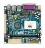
Chapter 1 MAINBOARD LAYOUT 4 - Via EPIA-EK10000G | User Manual - Page 13
BACK PANEL LAYOUT Specifications 5 - Via EPIA-EK10000G | User Manual - Page 14
and mic-in) Serial port 1 Parallel port PS/2 mouse port PS/2 keyboard port RJ45 ports USB 2.0 ports VGA port SLOTS Port DDR DIMM PCI Description Memory module slot Expansion card slot Page 15 13 14 13 13 14 14 13 Page 11 26 6 - Via EPIA-EK10000G | User Manual - Page 15
ONBOARD CONNECTORS Connector ATXPWR COM 2/3/4 CPUFAN SIR DIO F_AUDIO F_PANEL IDE 1-2 KBMS LVDS/TTL/DVI SATA 1-2 CD-In SMBus SYSFAN USB 3-6 Description Power cable connector COM port 2/3/4 pin headers CPU fan connector Fast Infrared Radiation connector Digital I/O connector Front Audio connector - Via EPIA-EK10000G | User Manual - Page 16
CHAPTER 2 Installation This chapter provides you with information about hardware installation procedures. It is recommended to use a grounded wrist strap before handling computer components. Electrostatic discharge (ESD) can damage some components. 8 - Via EPIA-EK10000G | User Manual - Page 17
Installation CPU The VIA EPIA-EK Mini-ITX mainboard includes an embedded VIA Luke CoreFusion™ Processor. The VIA Luke CoreFusion™ Processor provides ultralow power consumption and advanced thermal dissipation properties and features a fanless design. The VIA Luke CoreFusion™ Processor requires only - Via EPIA-EK10000G | User Manual - Page 18
Chapter 2 CPU Fan and System Fan: CPUFAN and SYSFAN The CPUFAN (CPU fan) and SYSFAN (system fan) run on +12V and maintain system cooling. When connecting the wire to the connectors, always be aware that the red wire is the Positive and should be connected to the +12V. The black wire is Ground and - Via EPIA-EK10000G | User Manual - Page 19
MODULE INSTALLATION The VIA EPIA-EK Mini-ITX mainboard provides one 184-pin DIMM slot for DDR 400 SDRAM memory modules and supports the memory size up to 1GB. DIMM DDR SDRAM Module Installation Procedures • Locate the DIMM slot in the motherboard. • Unlock a DIMM slot by pressing the retaining - Via EPIA-EK10000G | User Manual - Page 20
Chapter 2 CONNECTING THE POWER SUPPLY The VIA EPIA-EK Mini-ITX mainboard supports a conventional ATX power supply for the power system. Before inserting the power supply connector, always make sure that all components are installed correctly to ensure - Via EPIA-EK10000G | User Manual - Page 21
BACK PANEL PORTS The back panel has the following ports: Installation Keyboard and Mouse The green 6-pin connector is for a PS/2 mouse. The purple connector is for a PS/2 keyboard. Serial port: COM 1 The green 9-pin COM 1 port is for pointing devices or other serial devices. VGA Out The blue 15- - Via EPIA-EK10000G | User Manual - Page 22
Chapter 2 RJ45 10/100 LAN and USB 2.0 ports The mainboard provides two standard RJ-45 and four 4pin Universal Serial Bus (USB) 2.0 ports. These ports allow connection to a Local Area Network (LAN) through a network hub - Via EPIA-EK10000G | User Manual - Page 23
5.1 6-channel audio output. You can enable the function by clicking the "Vinyl Audio" icon on your desktop after installing the audio driver. After completing the previous installation, connect the speakers to the 3-jack connectors on the back panel. Shown below are the corresponding connections - Via EPIA-EK10000G | User Manual - Page 24
Chapter 2 CONNECTORS Hard Disk Connectors: IDE1 & IDE2 The mainboard has a 32-bit Enhanced IDE and Ultra DMA 133/100/66 controller that provides PIO mode 0~4, Bus Master, and Ultra DMA 133/100/66 functions. - Via EPIA-EK10000G | User Manual - Page 25
Installation Case Connector: F_PANEL The F_PANEL pin header allows you to connect the power switch, reset switch, power LED, sleep LED, HDD LED and the case speaker. F_PANEL Pin Signal 1 +5VDUAL 3 +5VDUAL 5 -PLED 7 +5V 9 NC 11 NC 13 SPEAK 15 Key Pin Signal 2 +5V 4 HD_LED 6 - Via EPIA-EK10000G | User Manual - Page 26
Chapter 2 Serial ATA Connectors: SATA1 and SATA2 These next generation connectors support the thin Serial ATA cables for primary internal storage devices. The current Serial ATA interface allows up to 150 MB/s data transfer rate, faster than - Via EPIA-EK10000G | User Manual - Page 27
Installation USB Pin Connector: USB 3-6 The mainboard provides 2 front USB pin headers, allowing up to 4 additional USB2.0 ports up to maximum throughput of 480 Mbps. Connect each 2-port USB cable into the - Via EPIA-EK10000G | User Manual - Page 28
Chapter 2 Serial Port Connector: COM 2/3/4 COM2/3/4 pin headers can be used to attach additional ports for serial mouse or other serial devices. Pin Signal 1 RIN12 3 DOUT22 5 GND 7 DOUT12 9 XRI2# Pin Signal 2 RIN32 4 DOUT32 6 RIN22 8 RIN42 10 Key COM 1 2 9 10 Digital I/O - Via EPIA-EK10000G | User Manual - Page 29
Installation Front Panel Audio Connector: F_AUDIO This is an interface for the VIA front panel audio cable that allow convenient connection and control of audio devices. By default, the pins labeled LINE_OUT_R / NEXT_R and the pins LINE_OUT_L / NEXT_L - Via EPIA-EK10000G | User Manual - Page 30
: JLVDS_DVI This connector works as the interface to multi display devices. An additional daughter card is required for a certain display support. Daughter cards for LVDS and DVI are currently available respectively. Pin Signal 1 FPDVIHS 3 FPDVIDE 5 SMB2_CK 7 SMB2_DA 9 +12V 11 +12V 13 - Via EPIA-EK10000G | User Manual - Page 31
: ENPVDD: Enable Panel VDD power ENVEE: Enable panel VEE power FPD: Graphic Flat Panel Device signals Installation KBMS Connector: KBMS The mainboard provides a PS2 pin header to attach a PS2 keyboard and mouse. Pin Signal 1 +5V Dual 3 KB_CLK 5 EKBCLK 7 Mouse_CLK 9 EMSCLK Pin Signal - Via EPIA-EK10000G | User Manual - Page 32
1 and 2 while the system is off. Return the jumper to pins 2 and 3 afterwards. Setting the jumper while the system is on will damage the mainboard. Keep Setting Keep CMOS setting Clear CMOS setting 1 2 3 OFF ON ON ON ON OFF 123 Clear 123 Caution: Except when clearing the RTC RAM, never - Via EPIA-EK10000G | User Manual - Page 33
Installation BIOS Write Protection: WP This jumper allows you to protect from flashing the BIOS. BIOS Write WP Protection setting: pin1 = /WP & /TBL, pin2 = GND, short 1-2. 1 LVDS Interface Selector: LVDS_DVI LVDS_DVI pin header can be used to switch between 24-bit and Dual 12-bit LVDS interface - Via EPIA-EK10000G | User Manual - Page 34
Chapter 2 SLOTS Peripheral Component Interconnect: PCI The PCI slot allows you to insert PCI expansion card. When adding or removing expansion card, first unplug the power supply. Read the documentation for the expansion card if any changes to the system are necessary. PCI PCI Interrupt Request - Via EPIA-EK10000G | User Manual - Page 35
CHAPTER 3 BIOS Setup This chapter gives a detailed explanation of the BIOS setup functions. 27 - Via EPIA-EK10000G | User Manual - Page 36
Chapter 3 ENTERING SETUP Power on the computer and press during the beginning of the boot sequence to enter the BIOS setup menu. If you missed the BIOS setup entry point, you may restart the system and try again. 28 - Via EPIA-EK10000G | User Manual - Page 37
CONTROL KEYS Keys Up Arrow Down Arrow Left Arrow Right Arrow Enter Escape Page Up / + Page Down / F1 F5 F6 F7 F9 F10 BIOS Setup Description Move to the previous item Move to the next item Move to the item in the left side Move to the item in the right side Select the item Jumps to the Exit menu or - Via EPIA-EK10000G | User Manual - Page 38
Chapter 3 NAVIGATING THE BIOS MENUS The main menu displays all the BIOS setup categories. Use the control keys Up/Down arrow keys to select any item/sub-menu. Description of the selected/highlighted category is displayed at the bottom of the screen. An arrow symbol next to a field indicates that a - Via EPIA-EK10000G | User Manual - Page 39
BIOS Setup GETTING HELP The BIOS setup program provides a "General Help" screen. You can display this screen from any menu/sub-menu by pressing . The help screen displays the keys for using and navigating the BIOS setup. Press to exit the help screen. 31 - Via EPIA-EK10000G | User Manual - Page 40
system configurations. Advanced BIOS Features Use this menu to set the advanced features available on your system. Advanced Chipset Features Use this menu to set chipset specific features and optimize system performance. Integrated Peripherals Use this menu to set onboard peripherals features. Power - Via EPIA-EK10000G | User Manual - Page 41
PC Health Status This menu shows the PC health status. BIOS Setup Frequency/Voltage Control Use this menu to set the system frequency and voltage control. Load Fail-Safe Defaults Use this menu option to load the BIOS default settings for minimal and stable system operations. Load Optimized - Via EPIA-EK10000G | User Manual - Page 42
20 : 20 [None] [QUANTUM FIREBALLP AS] [None] [None] Item Help Menu Level Change the day, month, year and century Halt On Base Memory Extended Memory Total Memory [All , But Keyboard] 640K 195584K 196608K : Move Enter: Select +/-/PU/PD: Value F10: Save F5: Previous Values F6: Fail-Safe Defaults - Via EPIA-EK10000G | User Manual - Page 43
table. The hard disk will not work properly if you enter incorrect information in this category. Select "Auto" whenever possible. If you select "Manual", make sure the information is from your hard disk vendor or system manufacturer. Below is a table that details required hard drive information when - Via EPIA-EK10000G | User Manual - Page 44
Chapter 3 ADVANCED BIOS FEATURES Phoenix - AwardBIOS CMOS Setup Utility Advanced BIOS Features Hard Disk Boot Priority Virus Warning CPU Internal Cache Processor Number Feature Quick Power On Self Test First Boot Device Second Boot Device Third Boot Device Boot Other Device Boot Up NumLock Status - Via EPIA-EK10000G | User Manual - Page 45
BIOS Setup Quick Power On Self-Test Shortens Power On Self-Test (POST) cycle to enable shorter boot up time. Setting Enabled Disabled Description Shorten Power On Self Test (POST) cycle and bootup time Standard Power On Self Test (POST) First/Second/Third Boot Device Set the boot device sequence - Via EPIA-EK10000G | User Manual - Page 46
Chapter 3 Typematic Rate (Chars/Sec) This item sets the rate (characters/second) at which the system retrieves a signal from a depressed key. Settings: [6, 8, 10, 12, 15, 20, 24, 30] Typematic Delay (Msec) This item sets the delay between when the key was first pressed and when the system begins to - Via EPIA-EK10000G | User Manual - Page 47
HARD DISK BOOT PRIORITY BIOS Setup Phoenix - AwardBIOS CMOS Setup Utility Hard Disk Boot Priority 1. Pri. Master : 2. Pri. Slave : 3. Sec. Master : 4. Sec. Slave : 5. USBHDD0 : 6. USBHDD1 : 7. USBHDD2 : 8. Bootable Add-In Cards Item Help Menu Level Use < > or < > to select a device, then press < - Via EPIA-EK10000G | User Manual - Page 48
Defaults ESC: Exit F1: General Help F7: Optimized Defaults Caution: The Advanced Chipset Features menu is used for optimizing the chipset functions. Do not change these settings unless you are familiar with the chipset. Display Card Priority This setting specifies which VGA card is your primary - Via EPIA-EK10000G | User Manual - Page 49
BIOS Setup Panel Type This setting refers to the native resolution of the display being used with the system. Key in a HEX number. Settings: [ 640x480 : 1 :On, 1280x768 : 1 :On, 1600x1200 : 2 :On, 1024x768 : 2 :On, 1280x768 : 1 :Off, 1600x1200 : 2 :Off] 800x600 : 1 :On, 1280x1024 : 2 :On, - Via EPIA-EK10000G | User Manual - Page 50
Chapter 3 AGP & P2P BRIDGE CONTROL Phoenix - AwardBIOS CMOS Setup Utility AGP & P2P Bridge Control AGP Aperture Size AGP 2.0 Mode VGA Share Memory Size Direct Frame Buffer [128M] [4x] [64M] [Enabled] Item Help Menu Level : Move Enter: Select +/-/PU/PD: Value F10: Save F5: Previous Values F6: - Via EPIA-EK10000G | User Manual - Page 51
CPU & PCI BUS CONTROL BIOS Setup VLink mode selection Phoenix - AwardBIOS CMOS Setup Utility CPU & PCI Bus Control [Mode 1] Item Help Menu Level : Move Enter: Select +/-/PU/PD: Value F10: Save F5: Previous Values F6: Fail-Safe Defaults ESC: Exit F1: General Help F7: Optimized Defaults V- - Via EPIA-EK10000G | User Manual - Page 52
Mode [Enabled] [Enabled] [Enabled] [Enabled] [RAID] Menu Level AC97 Audio VIA OnChip LAN 10/100 LAN Boot ROM Onboard LAN GigaLAN Boot ROM [Auto] [ The integrated peripheral controller contains an IDE interface with support for two IDE channels. Setting Enabled Disabled Description Activates - Via EPIA-EK10000G | User Manual - Page 53
two SATA plus two PATA hard disk drives Only SATA supports RAID AC'97 Audio Auto allows the mainboard to detect whether an audio device is used. If the device is detected, the onboard VIA AC'97 (Audio Codec'97) controller will be enabled; otherwise, it is disabled. Disable the controller if - Via EPIA-EK10000G | User Manual - Page 54
] USB Emulation Set this field to choose the USB emulation. When set to "OFF ", do not support any USB device on DOS. When set to "KB/MS", support USB legacy keyboard and mouse, no support USB storage. And set to "ON", support USB legacy keyboard, mouse and storage. Settings: [OFF, KB/MS, ON] 46 - Via EPIA-EK10000G | User Manual - Page 55
SUPER IO DEVICE BIOS Setup Onboard Serial Port 1 Onboard Serial Port 2 UART Mode Select RxD, TxD Active IR Transmission Delay UR2 Duplex Mode Use IR Pins Phoenix - AwardBIOS CMOS Setup Utility SuperIO Device [3F8/IRQ4] [2F8/IRQ3] [Normal] [Hi,Hi] [Disabled] [Half] [IR-Rx2Tx2] Item Help Menu - Via EPIA-EK10000G | User Manual - Page 56
Chapter 3 Use IR Pins Settings: [RxD2.TxD2, IR-Rx2Tx2] Onboard Parallel Settings: [Disabled, 378/IRQ7, 278/IRQ5, 3BC/IRQ7] Parallel Port Mode Settings: [SPP, EPP, ECP, ECP+EPP, Normal] EPP Mode Select Settings: [EPP1.9, EPP1.7] ECP Mode Use DMA Settings: [1, 3] UART 3/4 Settings: [Disabled, 3F8, 2F8 - Via EPIA-EK10000G | User Manual - Page 57
(POS): System in low power mode S3(STR): All components are powered off except memory. S1 & S3: Depends on OS to select S1 or S3 : Move Enter POS) is a low power state. In this state, no system context (CPU or chipset) is lost and hardware maintains all system contexts. S3/Suspend To RAM (STR) is - Via EPIA-EK10000G | User Manual - Page 58
a normal power-on/-off button Run VGABIOS if S3 Resume Select whether to run VGA BIOS if resuming from S3 state. necessary for older VGA drivers. This is only Settings: [Auto, Yes, No] AC Loss Auto Restart The field defines how the system will respond after an AC power loss during - Via EPIA-EK10000G | User Manual - Page 59
PERIPHERAL ACTIVITIES BIOS Setup Phoenix - AwardBIOS CMOS Setup Utility Peripherals Activities VGA Event LPT & COM Event HDD Event PCI Master Event [OFF] [COM] [ON] [OFF] PS2KB Wakeup Select [Hot Key] PS2MS Wakeup from S3/S4/S5[Disabled] PS2KB Wakeup from S3/S4/S5[Disabled] USB Resume [ - Via EPIA-EK10000G | User Manual - Page 60
Chapter 3 PS2KB Wakeup Select When selecting "Password", press or to change password. The maximum number of characters is eight. "PS2MS Wakeup from S3/S4/S5" and "PS2KB Wakeup from S3/S4/S5" will be disabled while changing the password. Settings: [Hot Key, Password] PS2MS - Via EPIA-EK10000G | User Manual - Page 61
BIOS Setup RTC Alarm Resume Sets a scheduled time and/or date to automatically power on the system. Settings: [Disabled, Enabled] Date (of Month) The field specifies the date for "RTC Alarm Resume". Resume Time (hh:mm:ss) The field specifies the time for "RTC Alarm Resume". 53 - Via EPIA-EK10000G | User Manual - Page 62
this by causing an IRQ to occur. After receiving the signal, when the operating system is ready, the system will interrupt itself and perform the service required by the IO device. 54 - Via EPIA-EK10000G | User Manual - Page 63
PNP/PCI CONFIGURATIONS BIOS Setup Phoenix - AwardBIOS CMOS Setup Utility PnP / PCI Configurations PNP OS Installed Reset Configuration Data Resources Controlled By IRQ Resources Assign IRQ For VGA Assign IRQ For USB [No] [Disabled] [Auto(ESCD)] Press Enter [Enabled] [Enabled] Item Help Menu - Via EPIA-EK10000G | User Manual - Page 64
to automatically configure all the Plug-and-Play compatible devices. Setting Auto(ESCD) Manual Description BIOS will automatically assign IRQ, DMA and memory base address fields Unlocks "IRQ Resources" for manual configuration Assign IRQ For VGA/USB Assign IRQ for VGA and USB devices. Settings - Via EPIA-EK10000G | User Manual - Page 65
F6: Fail-Safe Defaults ESC: Exit F1: General Help F7: Optimized Defaults Note: The items are adjustable only when "Resources Controlled By" is set to "Manual." IRQ Resources list IRQ 3/4/5/7/9/10/11/12/14/15 for users to set each IRQ a type depending on the type of device using the IRQ - Via EPIA-EK10000G | User Manual - Page 66
Chapter 3 PC HEALTH STATUS Phoenix - AwardBIOS CMOS Setup Utility PC Health Status CPU Temp. High Limit CPU Temp. Tolerance Chassis Temp. High Limit Chassis Temp. Tolerance [Disabled] [0 degC] [Disabled] [0 degC] Item Help Menu Level CPU Temperature Chassis Temperature CPU FAN Speed Chassis FAN - Via EPIA-EK10000G | User Manual - Page 67
Defaults DRAM Clock The chipset supports synchronous and asynchronous mode memory modules installed in your system. Changing the value from the factory setting is not recommended unless you install new memory that has a different performance rating than the original modules. Settings: [Manual - Via EPIA-EK10000G | User Manual - Page 68
for setting the length of time it takes to precharge a row in the memory module before the row becomes active. Longer values are safer but may not offer best performance. This field is only available when "DRAM Timing" is set to "Manual". Settings: [2T, 3T, 4T, 5T] Active to Precharge (Tras) This - Via EPIA-EK10000G | User Manual - Page 69
field is only available when "DRAM Timing" is set to "Manual". Settings: [2T, 3T] DRAM Command Rate This field is for setting how fast the memory controller sends out commands. Lower setting equals faster command rate. Note: Some memory modules may not be able to handle lower settings. Settings - Via EPIA-EK10000G | User Manual - Page 70
Advanced BIOS Features Load Fail-Safe Defaults Advanced Chipset Features Load Optimized Defaults Integrated Peripherals Set Supervisor fail-safe BIOS settings. These values are set by the mainboard manufacturer to provide a stable system with basic performance. Entering "Y" loads the default fail - Via EPIA-EK10000G | User Manual - Page 71
Advanced BIOS Features Load Fail-Safe Defaults Advanced Chipset Features Load Optimized Defaults Integrated Peripherals Set Supervisor optimized BIOS settings. The default optimized values are set by the mainboard manufacturer to provide a stable system with optimized performance. Entering "Y" - Via EPIA-EK10000G | User Manual - Page 72
Setup Utility Standard CMOS Features Advanced BIOS Features Advanced Chipset Features Integrated Peripherals Power Management Setup PnP / PCI Configurations now will clear any previously set password from CMOS memory. The new password will need to be reentered to be confirmed. To cancel the process - Via EPIA-EK10000G | User Manual - Page 73
BIOS Setup To disable the password, press when prompted to enter a new password. A message will show up to confirm disabling the password. To cancel the process press . Additionally, when a password is enabled, the BIOS can be set to request the password each time the system is booted. - Via EPIA-EK10000G | User Manual - Page 74
AwardBIOS CMOS Setup Utility Standard CMOS Features Frequency / Voltage Control Advanced BIOS Features Load Fail-Safe Defaults Advanced Chipset Features Load Optimized Defaults Integrated Peripherals Set Supervisor Password Power Management Setup Set User Password PnP / PCI Configurations - Via EPIA-EK10000G | User Manual - Page 75
EXIT WITHOUT SAVING BIOS Setup Phoenix - AwardBIOS CMOS Setup Utility Standard CMOS Features Advanced BIOS Features Advanced Chipset Features Integrated Peripherals Power Management Setup PnP / PCI Configurations PC Health Status Frequency / Voltage Control Load Fail-Safe Defaults Load Optimized - Via EPIA-EK10000G | User Manual - Page 76
This chapter gives you brief descriptions of each mainboard driver and application. You must install the VIA chipset drivers first before installing other drivers such as audio or VGA drivers. The applications will only function correctly if the necessary drivers are already installed. 68 - Via EPIA-EK10000G | User Manual - Page 77
utilities and software for enhancing the performance of the mainboard. If the CD is missing from the retail box, please contact the local dealer for the CD. Note: The driver utilities and software are updated from time to time. The latest updated versions are available at http://www.viaembedded.com - Via EPIA-EK10000G | User Manual - Page 78
the CD into the CD-ROM or DVD-ROM drive. The CD should run automatically after closing the CD-ROM or DVD-ROM drive. The driver utilities and software menu screen should then appear on the screen. If the CD does not run automatically, click on the "Start" button and select - Via EPIA-EK10000G | User Manual - Page 79
Installation CD CONTENT VIA 4in1 Drivers: Contains VIA ATAPI Vendor Support Driver (enables the performance enhancing bus mastering functions on ATA-capable Hard Disk Drives and ensures IDE device compatibility), AGP VxD Driver (provides service routines to your VGA driver and interface directly
-
 1
1 -
 2
2 -
 3
3 -
 4
4 -
 5
5 -
 6
6 -
 7
7 -
8
-
9
-
10
-
11
-
12
-
13
-
14
-
15
-
16
-
17
-
18
-
19
-
20
-
21
-
22
-
23
-
24
-
25
-
26
-
27
-
28
-
29
-
30
-
31
-
32
-
33
-
34
-
35
-
36
-
37
-
38
-
39
-
40
-
41
-
42
-
43
-
44
-
45
-
46
-
47
-
48
-
49
-
50
-
51
-
52
-
53
-
54
-
55
-
56
-
57
-
58
-
59
-
60
-
61
-
62
-
63
-
64
-
65
-
66
-
67
-
68
-
69
-
70
-
71
-
72
-
73
-
74
-
75
-
76
-
77
-
78
-
79
 |
 |

User’s Manual
EPIA-EK
Version 1.32
March 9, 2012