Via EPIA-MII12000G User Manual
Via EPIA-MII12000G - VIA EPIA MII 12000G Motherboard Manual
 |
View all Via EPIA-MII12000G manuals
Add to My Manuals
Save this manual to your list of manuals |
Via EPIA-MII12000G manual content summary:
- Via EPIA-MII12000G | User Manual - Page 1
User's Manual EPIA-MII Mini-ITX Mainboard Version 1.62 January 30, 2012 - Via EPIA-MII12000G | User Manual - Page 2
or translated into any language, in any form or by any means, electronic, mechanical, magnetic, optical, chemical, manual or otherwise without the prior written permission of VIA Technologies Incorporated. Trademarks Windows CE™, Windows XP™, Windows 2000™, Windows ME™, Windows 98™ and plug and play - Via EPIA-MII12000G | User Manual - Page 3
. This equipment generates, uses and can radiate radio frequency energy and, if not installed and used in accordance with the instruction manual, may cause harmful interference to radio communications. Operation of this equipment in a residential area is likely to cause harmful interference - Via EPIA-MII12000G | User Manual - Page 4
safety instructions carefully. 2. Keep this User's Manual for 8. Always unplug the power cord before inserting any add-on card or module. 9. All cautions and warnings on the equipment following situations arises, get the equipment checked by a service personnel: • The power cord or plug is damaged - Via EPIA-MII12000G | User Manual - Page 5
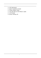
BOX CONTENTS • 1 x VIA Mainboard • 1 x Quick Installation Guide • 1 x Floppy Ribbon Cable • 1 x ATA-66/100/133 IDE Ribbon Cable • 1 x I/O Bracket • 1 x Driver Utilities CD i - Via EPIA-MII12000G | User Manual - Page 6
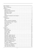
TABLE OF CONTENTS Box Contents i Table of Contents ii Chapter 1 1 Specifications 1 Mainboard Specifications 2 Mainboard Layout 4 Back Panel Ports 6 Slots 6 Onboard Connectors and Jumpers 7 Chapter 2 9 Installation 9 CPU 10 Memory Module Installation 12 Connecting the Power Supply 14 - Via EPIA-MII12000G | User Manual - Page 7
Set Supervisor / User Password 59 Save & Exit Setup 61 Exit Without Saving 62 Chapter 4 63 Driver Installation 63 Driver Utilities 64 CD Content 65 iii - Via EPIA-MII12000G | User Manual - Page 8
This page is intentionally left blank. iv - Via EPIA-MII12000G | User Manual - Page 9
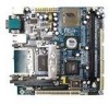
The ultra-compact and highly integrated VIA EPIA-MII Mini-ITX Mainboard is the smallest form factor mainboard specification available today, developed by VIA Technologies, Inc. as part of the company's open industry-wide total connectivity initiative. The mainboard enables the creation of an - Via EPIA-MII12000G | User Manual - Page 10
Chapter 1 MAINBOARD SPECIFICATIONS CPU • • • VIA C3 / EDEN EBGA Processor (onboard) Enhanced Ball Grid Array Package (EBGA) Internal L1 128KB and L2 64KB cache memory Chipset • VIA CLE266 North Bridge • VT8235 South Bridge Memory • 1 x DDR266 DIMM socket (up to 1 GB) Expansion Slots • 1 x PCI - Via EPIA-MII12000G | User Manual - Page 11
-on-LAN connector • 3 x Fan connectors (CPU Fan, System Fan, Fan 3) • 1 x LVDS connector (optional) • 1 x Serial port connector for second COM port • 1 x LPT port connector • 1 x SMBus connector • 1 x Video feature connector support (optional) BIOS • Award BIOS with 2/4Mbit flash memory Form Factor - Via EPIA-MII12000G | User Manual - Page 12
Chapter 1 MAINBOARD LAYOUT Back Panel 4 - Via EPIA-MII12000G | User Manual - Page 13
Add-On Module Specifications Placement of ADD-On Module CLE266 5 - Via EPIA-MII12000G | User Manual - Page 14
CF Slot COM 1 PS2-MS PS2-KB RCA_JACK RJ45 S-Video USB 1-2 VGA Out Description IEEE1394 (Firewire port) Line-Out, Line-In, Microphone PCMCIA Type II card slot CF Slot Serial port PS2 mouse port PS2 keyboard port RCA Video or SPDIF jack 10/100 NIC port S-Video port Universal Serial Bus - Via EPIA-MII12000G | User Manual - Page 15
Specifications ONBOARD CONNECTORS AND JUMPERS Connector/Jumper 1394_2 ATXPWR CD_IN CLEAR_CMOS COM2 F_AUDIO F_PANEL Fans FDD FIR SMBus IDE 1&2 KBMS LPT LVDS SPDIF_SEL USB 3/4 WOL Description IEEE 1394 connector ATX power cable connector Onboard CD audio cable connector Jumper to reset CMOS - Via EPIA-MII12000G | User Manual - Page 16
Chapter 1 This page is intentionally left blank. 8 - Via EPIA-MII12000G | User Manual - Page 17
CHAPTER 2 Installation This chapter provides you with information about hardware setup procedures. While installing the mainboard, carefully hold the components and closely follow the installation procedures. Some components may be damaged if they are installed incorrectly. It is recommended to use - Via EPIA-MII12000G | User Manual - Page 18
Chapter 2 CPU The VIA EPIA-MII Mini-ITX Mainboard includes an embedded VIA Eden Processor or VIA C3 E-Series Processor. The CPUFAN (CPU fan) and SYSFAN (system fan) run on +12V and maintain system cooling. When connecting the wire to the connectors, - Via EPIA-MII12000G | User Manual - Page 19
consumption and advanced thermal dissipation properties, the VIA Eden Processor features a fanless design. The VIA Eden Processor requires only a heatsink as shown. Installation Caution: This motherboard is not designed to support overclocking. Any attempt to operate beyond product specifications - Via EPIA-MII12000G | User Manual - Page 20
Chapter 2 MEMORY MODULE INSTALLATION The VIA EPIA-MII Mini-ITX Mainboard provides one 184-pin DIMM slot for DDR266 SDRAM memory modules. CLE266 DDR SDRAM Module Installation Procedures 1. Push the white retaining latches at either end - Via EPIA-MII12000G | User Manual - Page 21
Installation Available DDR SDRAM Configurations Refer to the table below for available DDR SDRAM configurations on the mainboard. Slot DIMM (Bank 0 & 1) Module Size 64MB, 128MB, 256MB, 512MB, 1GB Maximum System Memory Supported Total Memory 64MB - 1GB 64MB - 1GB 13 - Via EPIA-MII12000G | User Manual - Page 22
Chapter 2 CONNECTING THE POWER SUPPLY The VIA EPIA-MII Mini-ITX mainboard requires an ATX power supply to be connected. Before inserting the power supply connector, always make sure that all components are installed correctly to ensure - Via EPIA-MII12000G | User Manual - Page 23
NC 3 GND 4 VCC 5 Mouse Clock 6 NC Description Mouse data No connection Ground +5V Mouse clock No connection Keyboard Port: PS2_KB The mainboard provides a standard PS/2 keyboard connector for attaching a PS/2 keyboard. You can plug a PS/2 keyboard directly into this connector. Pin Signal - Via EPIA-MII12000G | User Manual - Page 24
into these ports. Pin Signal 1 VCC 2 -DATA 3 +DATA 4 GND Description +5V Negative data channel Positive data channel Ground RJ45 10/100 NIC Port The mainboard provides one standard RJ-45 port for connection to the Local Area Network (LAN). You can connect a network cable to the LAN port - Via EPIA-MII12000G | User Manual - Page 25
Data Data Terminal Ready Ground Data Set Ready Request To Send Clear To Send Ring Indicate Card Slots: PCMCIA, CF The mainboard comes with an add-on card that provides support for PCMCIA and CF cards. The CF slot supports both type I and type II. These slots are accessed on the same side as the - Via EPIA-MII12000G | User Manual - Page 26
be switched to Smart 5.1 6-channel audio output. You can enable the function by clicking the "Vinyl Audio" icon on your desktop after installing the audio driver. After completing the previous settings, you need to connect your speakers to the audio jacks as shown below. 18 - Via EPIA-MII12000G | User Manual - Page 27
CONNECTORS Installation Hard Disk Connectors: IDE1 & IDE2 The mainboard has a 32-bit Enhanced PCI IDE and Ultra DMA 66/100 controller that provides PIO mode 0~4, Bus Master, and Ultra DMA 66/100 functions. You - Via EPIA-MII12000G | User Manual - Page 28
Chapter 2 Case Connector: F_PANEL The F_PANEL connector block allows you to connect to the power switch, reset switch, power LED, HDD LED, SLED and the Speaker on the case. 2 16 Pin Signal Pin Signal 1 PWR LED+ 2 HDD LED+ 3 PWR LED+ 4 HDD LED- 1 5 PWR LED- 6 PW_BN+ 7 SPEAKER+ 8 - Via EPIA-MII12000G | User Manual - Page 29
Speaker The speaker from the system case is connected to this pin. Installation IrDA Infrared Module Connector: FIR This connector allows you to connect an IrDA Infrared module. You must configure the setting through the BIOS setup to activate the IR function. Pin Signal 1 VCC 2 IRRX2 3 - Via EPIA-MII12000G | User Manual - Page 30
Chapter 2 USB pin-header: USB3/4 The mainboard provides 1 USB pin-header connector, allowing up to 2 USB3+ 8 GND 10 GND Wake-on LAN: WOL This connector allows you to connect a network card with the Wake-On LAN function. The connector will power up the system when a signal is received through - Via EPIA-MII12000G | User Manual - Page 31
Data Set Ready 7 RTS Request To Send 8 CTS Clear To Send 9 RI Ring Indicate Installation Floppy Disk Drive Connector: FDD The floppy disk drive connector supports 360K, 720K, 1.2M, 1.44M, and 2.88M floppy disk types. 23 - Via EPIA-MII12000G | User Manual - Page 32
: CD_IN This connector is for the CD-ROM audio connector. Front Audio Panel: F_AUDIO This connector allows you to connect a front audio panel to the mainboard. Only the line-out and microphone functions are available for use on the front panel. To connect the front audio cable, first remove the two - Via EPIA-MII12000G | User Manual - Page 33
a System Management Bus device. Pin Signal 1 +3.3V 2 +3.3V 3 EL-ON 4 SMBCK 5 SMBDT 6 GND Installation LPT Pin Header: LPT The mainboard provides a pin header to attach a parallel port. Pin Signal 1 STROBE 3 DATA0 5 DATA1 7 DATA2 9 DATA3 11 DATA4 13 DATA5 15 DATA6 17 - Via EPIA-MII12000G | User Manual - Page 34
. This is an option that is added during the manufacturing process. If you would like a mainboard with the LVDS connector, please contact your vendor or sales contact for more information. Pin Signal Pin Signal 1 GFPDE 2 GFPD3 3 GFPD0 4 GFPD4 5 GFPD1 6 GFPD5 7 GFPD2 8 GFPCLK - Via EPIA-MII12000G | User Manual - Page 35
2 while the system is off. Then return it to the 2-3 pin position. Shorting the jumper while the system is on will damage the mainboard. The default position of the jumper is on pins 2 and 3. Setting 1 2 3 Keep OFF ON ON Clear ON ON OFF 1 2 3 4 SPDIF_SEL 3 2 1 CLE266 CLEAR_CMOS - Via EPIA-MII12000G | User Manual - Page 36
, make sure that you unplug the power supply first. Meanwhile, read the documentation for the expansion card to make any necessary hardware or software settings for the expansion card, such as jumpers, switches or BIOS configuration. PCI Interrupt Request Routing The IRQ, abbreviation of interrupt - Via EPIA-MII12000G | User Manual - Page 37
CHAPTER 3 BIOS Setup This chapter gives a detailed explanation of each BIOS setup functions. 29 - Via EPIA-MII12000G | User Manual - Page 38
Chapter 3 ENTERING SETUP Power on the computer and press Delete during the beginning of the boot sequence to enter the BIOS setup menu. If you missed the BIOS setup entry point, you may restart the system and try again. CONTROL KEYS Keys Up Arrow Down Arrow Left Arrow Right Arrow Enter Escape Page - Via EPIA-MII12000G | User Manual - Page 39
GETTING HELP BIOS Setup Main Menu The main menu displays all BIOS setup categories. Use the control keys Up/Down Arrow Keys to select any item/sub-menu. Description of the selected/highlighted category is displayed at the bottom of the screen. Sub-Menu If you find a right pointer symbol (as shown - Via EPIA-MII12000G | User Manual - Page 40
Chapter 3 MAIN MENU The Main Menu contains twelve setup functions and two exit choices. Use arrow keys to select the items and press Enter to accept or enter the submenu. Standard CMOS Features Use this menu to set basic system configurations. Advanced BIOS Features Use this menu to set the advanced - Via EPIA-MII12000G | User Manual - Page 41
PC Health Status This menu shows the PC health status. BIOS Setup Frequency/Voltage Control Use this menu to set the system frequency and voltage control. Load Fail-Safe Defaults Use this menu option to load the BIOS default settings for minimal and stable system operations. Load Optimized - Via EPIA-MII12000G | User Manual - Page 42
Chapter 3 STANDARD CMOS FEATURES Date The date format is . Day - day of the week, for example Friday. Read-only. Month - the month from Jan to Dec. Date - the date from 1 to 31. Year - the year, range from 1999 to 2098. Time The time format is Drive - Via EPIA-MII12000G | User Manual - Page 43
Zone Sector PIO Mode Ultra DMA Mode The name of this menu item will match the name of the menu. The settings are None, Auto, Manual. The settings are CHS, LBA, Large, Auto. Formatted size of the storage device. Number of cylinders Number of heads Write precompensation Cylinder location of the - Via EPIA-MII12000G | User Manual - Page 44
Chapter 3 ADVANCED BIOS FEATURES Virus Warning Set the Virus Warning feature for IDE Hard Disk boot sector protection. If the function is enabled, any attempt to write data into this area will cause a beep and warning message display on screen. Settings: Disabled and Enabled CPU L2 Cache ECC - Via EPIA-MII12000G | User Manual - Page 45
BIOS Setup First/Second/Third Boot Device Set the boot device sequence as BIOS attempts to load the disk operating system. Floppy LS120 HDD-0 SCSI CD-ROM HDD-1 HDD-2 HDD-3 ZIP100 USB-FDD USB-ZIP USB-CDROM USB-HDD LAN Disabled The system will boot from floppy drive. The system will boot from LS- - Via EPIA-MII12000G | User Manual - Page 46
Chapter 3 Typematic Rate Setting When Disabled, the following two items (Typematic Rate and Typematic Delay) are irrelevant. Keystrokes repeat at a rate determined by the keyboard controller in your system. When Enabled, you can select a typematic rate and typematic delay. Settings: Enabled and - Via EPIA-MII12000G | User Manual - Page 47
to the AGP without any translation. Settings: 4MB, 8MB, 16MB, 32MB, 64MB, 128MB and 256MB AGP Mode (Internal) This mainboard supports the AGP 4x interface. When the AGP 4x video card is used, it can transfer video data at 1066MB/s. AGP 4x is backward-compatible, leave the default 4x mode on if - Via EPIA-MII12000G | User Manual - Page 48
Chapter 3 AGP Fast Write When Enabled, the speed of the memory write operations will increase. Settings: Enabled and Disabled CPU to PCI POST Write When Enabled, CPU can write up to four words of data to the PCI write buffer before CPU must wait for PCI bus cycle to finish. If Disabled, CPU must - Via EPIA-MII12000G | User Manual - Page 49
1/2 The integrated peripheral controller contains an IDE interface with support for two IDE channels. Choose Enabled to activate each channel Card Priority This setting specifies which VGA card is your primary graphics adapter. Settings: PCI Slot and AGP Frame Buffer Size This setting instructs - Via EPIA-MII12000G | User Manual - Page 50
'97 Audio Auto allows the mainboard to detect whether an audio device is used. If the device is detected, the onboard VIA AC'97 (Audio Codec'97) controller will be enabled; if not, it is disabled. Disable the controller if you want to use other controller cards to connect to an audio device - Via EPIA-MII12000G | User Manual - Page 51
mode, choose EPP. By choosing ECP, the onboard parallel port will operate in ECP mode. Choosing ECP + EPP will allow the onboard parallel port to support both the ECP and EPP modes simultaneously. Settings: SPP, EPP, ECP, ECP + EPP 43 - Via EPIA-MII12000G | User Manual - Page 52
EPP 1.7 ECP Mode Use DMA ECP (Extended Capabilities Port) has two DMA channels that it can use. The default channel is 3. However, some expansion cards may use channel 3 as well. To solve this conflict, change the ECP channel to 1. Select a DMA channel for the port. Settings: 1, 3 Onboard Fast IR - Via EPIA-MII12000G | User Manual - Page 53
POWER MANAGEMENT SETUP BIOS Setup The Power Management Setup menu configures the system to most effectively save energy while operating in a manner consistent with your own style of computer use. ACPI Suspend Type Set the power saving mode for ACPI function. Settings are: S1(POS) S3(STR) S1 & S3 - Via EPIA-MII12000G | User Manual - Page 54
/-off button Run VGABIOS if S3 Resume Select whether to run VGA BIOS if resumed from S3 state. This is only necessary for older VGA drivers, select Auto if in doubt. Settings: Auto, Yes and No AC Loss Auto restart The field defines how the system will act after an AC - Via EPIA-MII12000G | User Manual - Page 55
BIOS Setup Peripheral Activities Press Enter to enter the sub-menu and the following screen appears: VGA Event Decide whether or not the power management unit should monitor VGA activities. Settings: Off and On LPT & COM Event Decide whether or not the power management unit should monitor parallel - Via EPIA-MII12000G | User Manual - Page 56
devices can wake the system from suspend state. Settings: Disabled and Enabled PowerOn by PCI Card Decide whether or not any PCI card can power up the system or resume from suspend state. Such PCI cards include LAN, onboard USB ports, etc. Settings: Disabled and Enabled Wake On LAN/Ring Connector - Via EPIA-MII12000G | User Manual - Page 57
this by causing an IRQ to occur. After receiving the signal, when the operating system is ready, the system will interrupt itself and perform the service required by the IO device. 49 - Via EPIA-MII12000G | User Manual - Page 58
be initialized by the PnP operating system like Windows 95 or 98/98SE. When set to No, BIOS will initialize all the PnP cards. Set to Yes the operating system is Plug & Play capable. Settings: No and Yes Reset Configuration Data Normally, you leave this field Disabled. Select Enabled - Via EPIA-MII12000G | User Manual - Page 59
and Play compatible devices. Choose Auto(ESCD) if unsure, the BIOS will automatically assign IRQ, DMA and memory base address fields. Settings: Auto (ESCD) and Manual Assign IRQ For VGA/USB Assign IRQ for VGA and USB devices. Settings: Disabled and Enabled 51 - Via EPIA-MII12000G | User Manual - Page 60
Chapter 3 IRQ Resources The items are adjustable only when Resources Controlled By is set to Manual. Press Enter and you will enter the sub-menu of the items. IRQ Resources list IRQ 3/4/5/7/9/10/11/12/14/15 for users to set - Via EPIA-MII12000G | User Manual - Page 61
BIOS Setup PC HEALTH STATUS This section shows the status of your CPU, fan, warning for overall system status. The PC Health Status displays the current status of all of the monitored hardware devices/components such as CPU voltages, temperatures and fan speeds. 53 - Via EPIA-MII12000G | User Manual - Page 62
FREQUENCY / VOLTAGE CONTROL DRAM Clock The chipset supports synchronous and asynchronous mode between host clock and install new memory that has a different performance rating than the original modules. Settings: Manual and By SPD DRAM CAS Latency This item adjusts the speed it takes for the - Via EPIA-MII12000G | User Manual - Page 63
row becomes active. Longer values are safer but may not offer the best performance. This field is only available when "DRAM Timing" is set to "Manual". Settings: 2T, 3T Active to Precharge (Tras) This field controls the length of time it a row stays active before precharging. Longer values are safer - Via EPIA-MII12000G | User Manual - Page 64
for the memory module. Settings: 2.8V, 2.7V, 2.6V, Default CPU Clock This field sets the CPU clock speed. Spread Spectrum When the mainboard's clock generator pulses, the extreme values (spikes) of the pulses creates EMI (Electromagnetic Interference). The Spread Spectrum function reduces the EMI - Via EPIA-MII12000G | User Manual - Page 65
on the main menu allows users to restore all the BIOS settings to the default Fail Safe values. These values are set by the mainboard manufacturer to provide a minimal and stable system. When you select Load-Fail Safe Defaults, a message as below appears: Entering Y loads the default BIOS values - Via EPIA-MII12000G | User Manual - Page 66
settings to the default Optimized values. The Optimized Defaults are the default values also set by the mainboard manufacturer for both optimized and stable performance of the mainboard. When you select Load Optimized Defaults, a message as below appears: Entering Y loads the default values that are - Via EPIA-MII12000G | User Manual - Page 67
SET SUPERVISOR / USER PASSWORD BIOS Setup When you select this function, a message as below will appear on the screen: Type the password, up to eight characters in length, and press Enter. The password typed now will clear any previously set password from CMOS memory. You will be prompted to - Via EPIA-MII12000G | User Manual - Page 68
Chapter 3 Additionally, when a password is enabled, you can also have BIOS to request a password each time the system is booted. This would prevent unauthorized use of your computer. The setting to determine when the password prompt is required is the Security Option of the Advanced BIOS Features - Via EPIA-MII12000G | User Manual - Page 69
BIOS Setup SAVE & EXIT SETUP When you want to quit the Setup menu, you can select this option to save the changes and quit. A message as below will appear on the screen: Entering Y will allow you to quit the Setup Utility and save the user setup changes to RTC CMOS. Entering N will return to the - Via EPIA-MII12000G | User Manual - Page 70
Chapter 3 EXIT WITHOUT SAVING When you want to quit the Setup menu, you can select this option to abandon the changes. A message as below will appear on the screen: Entering Y will allow you to quit the Setup Utility without saving any changes to RTC CMOS. Entering N will return to the Setup Utility - Via EPIA-MII12000G | User Manual - Page 71
This chapter gives you brief descriptions of each mainboard driver and application. You must install the VIA chipset drivers first before installing other drivers such as audio or VGA drivers. The applications will only function correctly if the necessary drivers are already installed. 63 - Via EPIA-MII12000G | User Manual - Page 72
, please contact the local dealer for the CD. Note: The driver utilities and software are updated from time to time. Please visit our website (http://www.viaembedded.com/) for the latest updated mainboard driver and utilities. Running the Driver Utilities CD To start using the CD, just simply insert - Via EPIA-MII12000G | User Manual - Page 73
in this CD are: • VIA 4in1 Drivers: Contains VIA ATAPI Vendor Support Driver (enables the performance enhancing bus mastering functions on ATA-capable Hard Disk Drives and ensures IDE device compatibility), AGP VxD Driver (provides service routines to your VGA driver and interface directly to
-
 1
1 -
 2
2 -
 3
3 -
 4
4 -
 5
5 -
 6
6 -
 7
7 -
8
-
9
-
10
-
11
-
12
-
13
-
14
-
15
-
16
-
17
-
18
-
19
-
20
-
21
-
22
-
23
-
24
-
25
-
26
-
27
-
28
-
29
-
30
-
31
-
32
-
33
-
34
-
35
-
36
-
37
-
38
-
39
-
40
-
41
-
42
-
43
-
44
-
45
-
46
-
47
-
48
-
49
-
50
-
51
-
52
-
53
-
54
-
55
-
56
-
57
-
58
-
59
-
60
-
61
-
62
-
63
-
64
-
65
-
66
-
67
-
68
-
69
-
70
-
71
-
72
-
73
 |
 |

User’s Manual
EPIA-MII
Mini-ITX Mainboard
Version 1.62
January 30, 2012