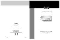
Viking 18%20Inch%20H.%20Chimney%20Wall%20Hood Installation Instructions - Page 2

Table of Contents, IMPORTANT

Page 2 highlights

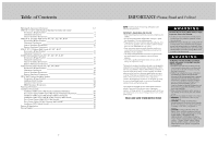
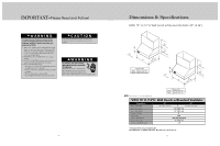
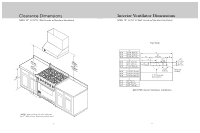
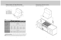
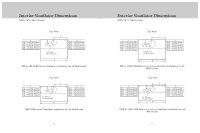
Table of Contents Warnings & Important Information 3-4 VWH 10" H./12"H. Wall Hoods w/Standard Ventilator 30", & 36" Dimensions & Specifications 5 Clearance Dimensions 6 Interior Ventilator Dimensions 7 VWH 18"H. 24"Deep Wall Hoods 30", 36", 42", 48", & 60" Dimensions & Specifications 8 Clearance Dimensions 9 Interior Ventilator Dimensions 10 Exterior Ventilator Dimensions 11 VWHO 18"H. Outdoor Wall Hoods 36", 48", & 60" Dimensions & Specifications 12 Clearance Dimensions 13 VCWH Chimney Wall Hoods 30", 36", 42", 48", & 60" Dimensions & Specifications 14 Clearance Dimensions 15 Interior Ventilator Dimensions 16 Exterior Ventilator Dimensions 17 VCIH Chimney Island Hoods 36", 42", 54", & 66" Dimensions & Specifications 18 Clearance Dimensions 19 Interior Ventilator Dimensions 20 Exterior Ventilator Dimensions 21 VBCV Wall Custom Ventilator System Dimensions & Specifications 22 Installing Hood Canopy 23 Clearance Dimensions 24 VBCV Ventilator Dimensions 25 Planning Information 27 Installation Procedures Installation (VWH 12"H. Wall Hoods w/Standard Ventilator 28 Duct Cover Option (VWH 12"H. Wall Hoods w/Standard Ventilator 30 Installation (VWH 12"H. Wall Hoods w/Recirculating Kit 30 Installation (VWH 18"H. Wall & VCWH Chimney Wall Hoods 33 Duct Cover Option (VWH 18"H. Wall Hoods 34 Duct Cover Option (VCWH Chimney Wall Hoods 35 Installation (VCIH Island Hoods 36 Service & Registration 38 Wiring Diagram 39 2 IMPORTANT-Please Read and Follow! NOTE: If installing hood with warming shelf panel, install warming shelf panel first. IMPORTANT - PLEASE READ AND FOLLOW • Before beginning, please read these instructions completely and carefully. • Do not remove permanently affixed labels, warnings, or plates from the product. This may void the warranty. • Please observe all local and national codes and ordinances. If no local codes are applicable, wire in accordance with the National Electrical Code, ANSI/NFPA 70-latest edition. • Damp environment approved models should be installed in a covered non-enclosed area and should be protected from the elements as much as possible. • The installer should leave these instructions with the consumer who should retain for local inspector's use and for future reference. • Check with a qualified and trained installer or local codes for makeup air requirement, if any. This hood is for residential installation only and is not designed for installation over a commercial product. Make sure power is off at the main circuit breaker or fuse box before making connections. To avoid risk of fire, electric shock, or injury to persons, turn off the electricity to the hood from the power supply before servicing or cleaning. Viking hoods are equipped with variable speed control blowers. These units will not function with a single speed ventilator. All Viking Range ventilator kits are designed specifically for use with Viking Range hoods. Use of any non-Viking Range ventilator kit will void the hood warranty. Viking hoods are equipped with the variable speed controls for blowers. These units will not function with a single speed ventilator. All Viking ventilator kits are designed specifically for use with Viking hoods. Use of any non-Viking ventilator kit will void the hood warranty. READ AND SAVE THESE INSTRUCTIONS WARNING To reduce the risk of fire, electric shock, or injury to persons, observe the following: • Use this unit only in the manner intended by the manufacturer. If you have any questions, contact the manufacturer. • Before servicing or cleaning unit, switch power off at service panel and lock service panel to prevent power from being switched on accidentally. When the service disconnecting means cannot be locked, securely fasten a prominent warning device, such as a tag, to the service panel. WARNING TO REDUCE THE RISK OF FIRE, ELECTRICAL SHOCK, OR INJURY TO PERSONS, OBSERVE THE FOLLOWING: 1. Installation work and electrical wiring must be done by qualified person(s) in accordance with all applicable codes and standards, including fire-rated construction. 2. Sufficient air is needed for proper combustion and exhausting of gases through the flute (chimney) of fuel burning equipment to prevent back drafting. Follow the heating equipment manufacturer's guideline and safety standards such as those published by the National Fire Protection Association (NFPA), and the American Society for Heating, Refrigeration and Air Conditioning Engineers (ASHRAE), and the local code authorities. 3. When cutting of drilling into wall or ceiling, do not damage electrical wiring and other hidden utilities. 4. Ducted fans must always be vented to the outdoors. 5. WARNING!: To reduce risk of fire, use only metal ductwork 6. CAUTION!: To reduce risk of fire and to properly exhaust air, be sure to duct air outside. Do not vent exhaust air into spaces within walls or ceilings, or into attics, crawl spaces, or garages. 7. CAUTION!: To Reduce the Risk of Fire and Electric Shock, Install this rangehood only with remote blower models manufactured by Viking, model numbers - DEV900/DEV1200, VEV900/VEV1200, OR DEV1500, VEV1500 or integral blowers manufactured by Viking, model numbers - DIV300, DIV440, DIV600, DIV800, DIV1200, VIV300, VIV600, or VIV1200. NOTE - Please refer inside for specific canopy/blower combinations. 3

  • 1
  • 2
  • 3
  • 4
  • 5
  • 6
  • 7
  • 8
  • 9
  • 10
  • 11
  • 12
  • 13
  • 14
  • 15
  • 16
  • 17
  • 18
  • 19
  • 20

3
NOTE:
If installing hood with warming shelf panel, install
warming shelf panel first.
IMPORTANT – PLEASE READ AND FOLLOW
• Before beginning, please read these instructions completely and
carefully.
• Do not remove permanently affixed labels, warnings, or plates
from the product. This may void the warranty.
• Please observe all local and national codes and ordinances. If no
local codes are applicable, wire in accordance with the National
Electrical Code, ANSI/NFPA 70-latest edition.
• Damp environment approved models should be installed in a
covered non-enclosed area and should be protected from the
elements as much as possible.
• The installer should leave these instructions with the consumer
who should retain for local inspector’s use and for future
reference.
• Check with a qualified and trained installer or local codes for
makeup air requirement, if any.
This hood is for residential installation only and is not designed for
installation over a commercial product. Make sure power is off at
the main circuit breaker or fuse box before making connections. To
avoid risk of fire, electric shock, or injury to persons, turn off the
electricity to the hood from the power supply before servicing or
cleaning. Viking hoods are equipped with variable speed control
blowers. These units will not function with a single speed
ventilator. All Viking Range ventilator kits are designed specifically
for use with Viking Range hoods. Use of any non-Viking Range
ventilator kit will void the hood warranty.
Viking hoods are equipped with the variable speed controls for
blowers. These units will not function with a single speed
ventilator. All Viking ventilator kits are designed specifically for use
with Viking hoods. Use of any non-Viking ventilator kit will void the
hood warranty.
READ AND SAVE THESE INSTRUCTIONS
TO REDUCE THE RISK OF FIRE, ELECTRICAL
SHOCK, OR INJURY TO PERSONS, OBSERVE
THE FOLLOWING:
1. Installation work and electrical wiring must be
done by qualified person(s) in accordance with
all applicable codes and standards, including
fire-rated construction.
2. Sufficient air is needed for proper combustion
and exhausting of gases through the flute
(chimney) of fuel burning equipment to prevent
back drafting. Follow the heating equipment
manufacturer’s guideline and safety standards
such as those published by the National Fire
Protection Association (NFPA), and the
American Society for Heating, Refrigeration and
Air Conditioning Engineers (ASHRAE), and the
local code authorities.
3. When cutting of drilling into wall or ceiling, do
not damage electrical wiring and other hidden
utilities.
4. Ducted fans must always be vented to the outdoors.
5.
WARNING!:
To reduce risk of fire, use only
metal ductwork
6.
CAUTION!:
To reduce risk of fire and to
properly exhaust air, be sure to duct air outside.
Do not vent exhaust air into spaces within walls
or ceilings, or into attics, crawl spaces, or
garages.
7.
CAUTION!:
To Reduce the Risk of Fire and
Electric Shock, Install this rangehood only with
remote blower models manufactured by Viking,
model numbers – DEV900/DEV1200,
VEV900/VEV1200, OR DEV1500, VEV1500 or
integral blowers manufactured by Viking, model
numbers – DIV300, DIV440, DIV600, DIV800,
DIV1200, VIV300, VIV600, or VIV1200. NOTE –
Please refer inside for specific canopy/blower
combinations.
WARNING
WARNING
To reduce the risk of fire, electric shock, or injury
to persons, observe the following:
• Use this unit only in the manner intended by the
manufacturer. If you have any questions, contact
the manufacturer.
• Before servicing or cleaning unit, switch power off
at service panel and lock service panel to prevent
power from being switched on accidentally. When
the service disconnecting means cannot be locked,
securely fasten a prominent warning device, such
as a tag, to the service panel.
2
Warnings & Important Information
________________________________________________________ 3-
4
VWH 10” H./12”H. Wall Hoods w/Standard Ventilator 30”, & 36”
Dimensions & Specifications _____________________________________________________ 5
Clearance Dimensions___________________________________________________________ 6
Interior Ventilator Dimensions ____________________________________________________ 7
VWH 18”H. 24”Deep Wall Hoods 30”, 36”, 42”, 48”, & 60”
Dimensions & Specifications ______________________________________________________ 8
Clearance Dimensions _____________________________________________________________ 9
Interior Ventilator Dimensions _____________________________________________________ 10
Exterior Ventilator Dimensions ___________________________________________________ 11
VWHO 18”H. Outdoor Wall Hoods 36”, 48”, & 60”
Dimensions & Specifications _____________________________________________________ 12
Clearance Dimensions __________________________________________________________ 13
VCWH Chimney Wall Hoods 30”, 36”, 42”, 48”, & 60”
Dimensions & Specifications _____________________________________________________ 14
Clearance Dimensions __________________________________________________________ 15
Interior Ventilator Dimensions ___________________________________________________ 16
Exterior Ventilator Dimensions ___________________________________________________ 17
VCIH Chimney Island Hoods 36”, 42”, 54”, & 66”
Dimensions & Specifications _____________________________________________________ 18
Clearance Dimensions___________________________________________________________ 19
Interior Ventilator Dimensions ___________________________________________________ 20
Exterior Ventilator Dimensions ___________________________________________________ 21
VBCV Wall Custom Ventilator System
Dimensions & Specifications
_____________________________________________________ 22
Installing Hood Canopy
_________________________________________________________ 23
Clearance Dimensions___________________________________________________________ 24
VBCV Ventilator Dimensions
_____________________________________________________ 25
Planning Information________________________________________________________________ 27
Installation Procedures
Installation (VWH 12”H. Wall Hoods w/Standard Ventilator) __________________________ 28
Duct Cover Option (VWH 12”H. Wall Hoods w/Standard Ventilator)___________________ 30
Installation (VWH 12”H. Wall Hoods w/Recirculating Kit)_____________________________ 30
Installation (VWH 18”H. Wall & VCWH Chimney Wall Hoods)
________________________ 33
Duct Cover Option (VWH 18”H. Wall Hoods)_______________________________________ 34
Duct Cover Option (VCWH Chimney Wall Hoods)
__________________________________ 35
Installation (VCIH Island Hoods)
__________________________________________________ 36
Service & Registration_______________________________________________________________ 38
Wiring Diagram ____________________________________________________________________ 39
Table of Contents
IMPORTANT—
Please Read and Follow!