Weider 148 English Manual - Page 8
Inner Cap into each end of the Fly Arm Pad Tube - weight system
 |
View all Weider 148 manuals
Add to My Manuals
Save this manual to your list of manuals |
Page 8 highlights
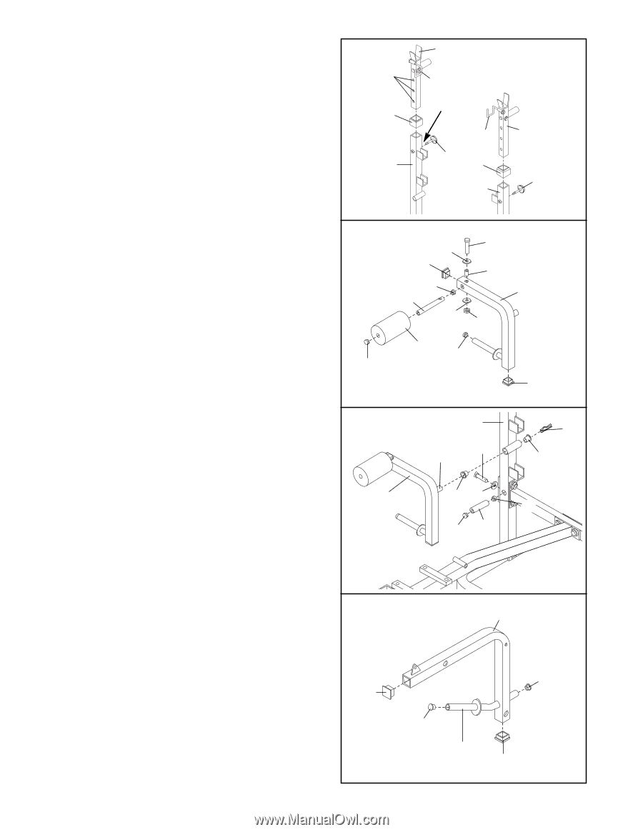
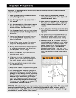
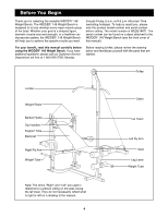
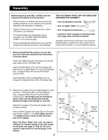
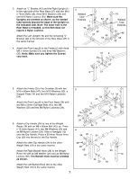
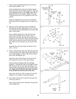
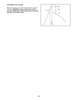
7. Press a 50mm Square Bushing (55) onto the top end of each Upright (1, 16). Slide the Weight Rest (19) with The Right Barbell Hook (28) down into the Right Upright (1). Align one of the adjustment holes in the Weight Rest with the adjustment hole in the Upright. Tighten the Large Threaded Knob (32) into the adjustment hole in the Upright. Attach the Weight Rest (19) with the Left Barbell Hook (30) to the Left Upright (16) in the same manner. 8. Attach a Fly Arm Pad Tube (22) to the Right Fly Arm (25) with an M8 x 50mm Bolt (13), an 11mm x 7mm Spacer (23), two M8 Washers (20) and an M8 Nylon Locknut (39). Press a 38mm Square Inner Cap (57) into each open end of the Right Fly Arm A (25). Press a 25.4mm Round Inner Cap (59) into the end of the weight tube on the Fly Arm. Press a 25.4mm Round Inner Cap into each end of the Fly Arm Pad Tube (22). Slide a Foam Pad (40) onto the Fly Arm Pad Tube. Assemble the Left Fly Arm (26, not shown) in the same manner. 9. Press a 19mm Round Inner Cap (58) into each end of a Fly Arm Stop (15). Attach the Fly Arm Stop (15) to the Right Upright (1) with an M8 x 30mm Screw (60) and an M8 Washer (20). Attach the other Fly Arm Stop (not shown) to the Left Upright (not shown) in the same manner. Press two Nylon Bushings (38) into the Right Upright (1). Lubricate the axle on the Right Fly Arm (25). Slide the axle into the Nylon Bushings in the Upright. Slide a Spring Clip (37) into the end of the axle. Make sure the Spring Clip locks into place in the drilled hole near the end of the axle. Attach the Left Fly Arm (26, not shown) to the Left Upright (16, not shown) in the same manner. 10. Tap a 38mm Square Inner Cap (57) into each end of the Leg Lever (4). Tap a 25.4mm Round Inner Cap (59) into each end of the weight tube. 7 Adjustment Holes 55 1 19 28 Adjustment Hole 30 32 55 16 19 32 8 59 20 57 59 22 20 13 23 25 39 40 59 57 9 1 37 Lubricate 60 Axle 38 25 38 20 58 58 15 10 4 59 57 59 Weight Tube 57 8
-
 1
1 -
2
-
 3
3 -
 4
4 -
 5
5 -
 6
6 -
 7
7 -
 8
8 -
 9
9 -
 10
10 -
 11
11 -
 12
12 -
 13
13 -
14
-
15
-
16
-
17
-
18
-
19
-
20
 |
 |