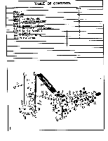
Weider 230 Bench English Manual - Page 7
Screws
 |
View all Weider 230 Bench manuals
Add to My Manuals
Save this manual to your list of manuals |
Page 7 highlights
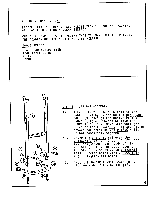
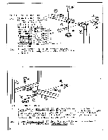
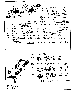
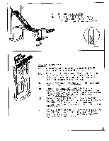
LOOSEN lOR 2 TURNS (:) REMOVE *I STEP 4 BACKREST PREPARATION 4A. Turn BACKREST(5) over to expose work area. Identify lower end of BAUKKESI (5) by checking the placement of LONG ANGLE IRON (14) The lower end of the BACKREST (5) is the end of the pad where the LONG ANGLE IRONS (14) extend past the pad. The MACHINE SCREW (S) on the lower end of the pad must be completely removed. ITT-MACHINE SCREW (S) on the opposite end of the same LONG ANGLE IRON (14) is only loosened 1 or 2 turns. 1, 13 0 • rj r -t 0 STEP 5 BACKREST AND SEAT ASSEMBLY 5A. BACKREST: Slide BACKREST ADj BAR (13) into any of the three hole patterns on the UPRIUHI (I)-to" aid in this assembly. With BACKREST (5) right-side up lower to MAIN FRAME (2). Slide secured LONG ANGLE IRON (14) over one side of pivot pin on MAIN FRAME (2). Swing freed LONG ANGLE IRON (14) over opposite of pivot pin on MAIN FRAME (2). Replace MACHINE SCREW (S) removed in Step 4. Tighten all Machine Screws! 5B. SEAT: Align threaded holes on SEAT (6) with holes on seat bracket on MAIN FRAME (2). Secure SEAT (6) with 2 MACHINE SCREWS (S). 6
-
 1
1 -
 2
2 -
 3
3 -
 4
4 -
 5
5 -
 6
6 -
 7
7 -
 8
8 -
 9
9
 |
 |
