Weider 9350 Instruction Manual - Page 12
Attach the V-pulley and a Long Cable Trap 50
 |
View all Weider 9350 manuals
Add to My Manuals
Save this manual to your list of manuals |
Page 12 highlights
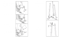
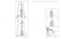
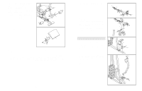
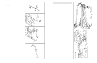
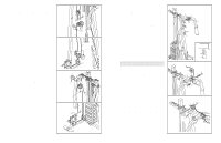
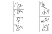
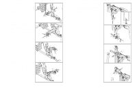
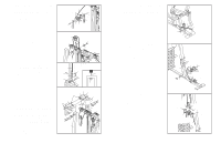
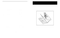
18. Wrap the High Cable (11) around a "V"-pulley (6). 18 Attach the "V"-pulley and a Long Cable Trap (50) to the Left Butterfly Arm (47) with an M10 x 60mm Bolt (7) and an M10 Nylon Locknut (21). Make sure the Cable Trap is oriented to hold the Cable in the groove of the "V"-pulley. Repeat this step with the Right Butterfly Arm (48). 7 50 6 11 47 48 21 19. Wrap the High Cable (11) around a 90mm Pulley 19 (15). Attach the Pulley to the Pulley Bracket (20) with an M10 x 47mm Bolt (103) and an M10 Nylon Locknut (21). Attach the Pulley Bracket (20) to the Top Frame (55) with an M10 Washer (9) and an M10 Nylon Locknut (21). Do not overtighten the Locknut. 55 20 11 103 21 9 15 21 20. Wrap the High Cable (11) under a 90mm Pulley 20 (15). Attach the Pulley and a pair of Pulley Covers (40) to the top hole in the Large "U"- bracket (90) with an M10 x 52mm Bolt (12) and an M10 Nylon Locknut (21). Make sure the small tabs on the Pulley Covers are on top. Small Tab 21. Attach the High Cable (11) to the bracket on the 21 Front Upright (42) with an M10 x 22mm Bolt (98), an M10 Washer (9), and an M10 Nylon Locknut (21). 40 21 9 21 11 11 40 15 12 90 98 42 12 37. Attach the Low Cable (69) to the Front Upright 37 (42) with an M8 x 80mm Shoulder Bolt (95), two M8 Washer (70), and an M8 Nylon Locknut (3). 42 95 70 69 70 3 38. Attach a 90mm Pulley (15) to the top hole in the 38 Swivel Bracket (81) with an M10 x 45mm Bolt (100) and an M10 Nylon Locknut (21). Locate the Carriage Cable (83), which has a ball 81 21 on one end and a eyelet on the other. Wrap the Cable around a 90mm Pulley (15). Attach the 15 Pulley to the bottom hole in the Swivel Bracket 83 (81) with an M10 x 45mm Bolt (100) and an M10 Nylon Locknut (21). 100 39. Wrap the Carriage Cable (83) around a 90mm 39 Pulley (15) and route it through the hole in the Carriage Upright (84). Attach the Pulley and a pair of Pulley Covers (40) to the bracket on the Carriage Upright with an M10 x 52mm Bolt (12) and an M10 Nylon Locknut (21). Make sure the 21 large tabs on the Pulley Covers are on the 40 83 side shown. 15 84 40. Wrap the Carriage Cable (83) up around a 90mm Pulley (15). Attach the Pulley and a pair of Pulley Covers (40) inside the indicated bracket on the Stabiliser (5) with an M10 x 105mm Bolt (106). Push the Bolt only through the first bracket. Make sure the large tabs on the Pulley Covers are on the side shown. Hold a 12.5mm Spacer (82) between the two brackets on the Stabiliser (5). Push the M10 x 105mm Bolt (106) through the Spacer, but not into the next bracket. Large Tab 40 12 40 Large Tab 40 15 106 83 40 82 5 17
-
 1
1 -
2
-
3
-
4
-
5
-
6
-
 7
7 -
 8
8 -
 9
9 -
 10
10 -
 11
11 -
 12
12 -
 13
13 -
 14
14 -
 15
15 -
 16
16 -
 17
17 -
18
 |
 |
