Weider 9350 Instruction Manual - Page 7
Insert the Curl Post 35 into the Seat Frame
 |
View all Weider 9350 manuals
Add to My Manuals
Save this manual to your list of manuals |
Page 7 highlights
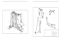
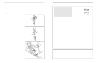
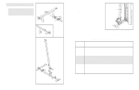
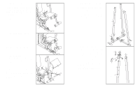
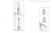
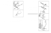
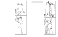
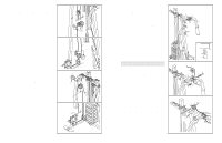
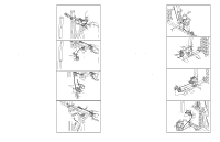
ATTACHING THE SEAT FRAME To attach the Seat Frame (36) to the Front Upright (42), slide one of the three slots in the bracket on the Seat Frame onto the pin on the Upright. Note: The Seat Frame can be adjusted to three different heights using the three slots. Secure the Seat Frame to the Upright with the M10 x 80mm Carriage Bolt (99) and the Seat Knob (49). For some exercises, the Seat Frame (36) must be removed. First, make sure that the chain is not attached to the leg lever. Next, remove the Seat Knob (49) and the M10 x 80mm Carriage Bolt (99) from the Seat Frame. Lift the Seat Frame off the Front Upright (42). Slot 49 99 Pin 36 42 ATTACHING THE LEG LEVER TO THE LOW CABLE To use the Leg Lever (29), the seat frame must be attached to the front upright (see ATTACHING THE SEAT FRAME above). Attach one end of the Chain (52) to the end of the Low Cable (69) with a Cable Clip (53). Attach the other end of the Chain to the bracket on the back of the Leg Lever (29) with another Cable Clip. ATTACHING THE CURL PAD To attach the Curl Pad (24) to the weight system, the seat frame must be attached to the front upright (see ATTACHING THE SEAT FRAME above). Remove the 38mm Square Inner Cap (32) from the Seat Frame (36). Insert the Curl Post (35) into the Seat Frame and secure it with the Curl Knob (51). Always remove the Curl Pad (24) when it is not in use, and replace the 38mm Square Inner Cap (32). To use the Curl Bar (67) to do curl exercises, attach one end of a Chain (52) to the Curl Bar with a Cable Clip (53). Attach the other end of the Chain to the indicated Eyebolt (109) on the Leg Lever (29) with a Cable Clip. 22 29 52 53 69 51 32 36 35 24 52 53 67 29 53 109 3. Attach the Support Upright (88) to the Stabiliser 3 (5) with the indicated two M10 x 55mm Carriage Bolts (1) and two M10 Nylon Locknuts (21). Do not tighten the M10 Nylon Locknuts yet. Make sure the Support Upright leans toward the center of the Stabiliser. Attach the Carriage Upright (84) to the Stabiliser (5) with the indicated two M10 x 55mm Carriage Bolts (1) and two M10 Nylon Locknuts (21). Do not tighten the M10 Nylon Locknuts yet. 88 84 21 21 21 21 1 4. Turn the Carriage Knob (73) counter clockwise 4 and pull it out as far as it will go. Slide the Carriage (89) onto the Carriage Upright (84) and engage the Knob into one of the adjustment holes in the Upright. Fully tighten the Knob. Make sure the Carriage is oriented as shown. Be careful not to scratch the decals on the Upright as you slide the Carriage over them. Attach the Swivel Bracket (81) to the Carriage (89) with an M10 x 158mm Bolt (108) and an M10 Nylon Locknut (21). Do not overtighten the M10 Locknuts; the Swivel Bracket must be able to pivot easily. Press two 60mm Square Inner Caps (101) into the top of the Carriage Upright (84) and the Support Upright (88). 5 1 101 108 101 89 21 81 84 73 88 Adjustment Hole 7
-
 1
1 -
 2
2 -
 3
3 -
 4
4 -
 5
5 -
 6
6 -
 7
7 -
 8
8 -
 9
9 -
 10
10 -
 11
11 -
 12
12 -
13
-
14
-
15
-
16
-
17
-
18
 |
 |
