Weider 9645 Instruction Manual - Page 11
Arm Assembly, Cable Assembly
 |
View all Weider 9645 manuals
Add to My Manuals
Save this manual to your list of manuals |
Page 11 highlights
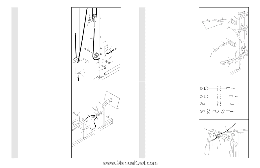
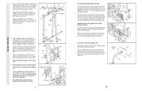
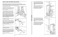
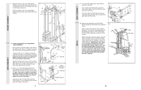
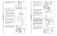
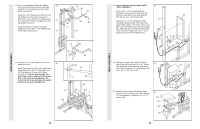
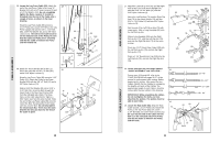
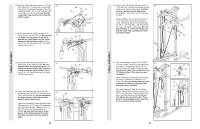
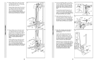
CABLE ASSEMBLY 38. Locate the Leg Press Cable (99). Attach the 38 end of the Leg Press Cable to the Long "U"- Bracket (57) with a 1/4" Nylon Locknut (2) and a 1/4" Flat Washer (10). Do not completely tighten the Nylon Locknut. It should be threaded onto the end of the Cable only a couple of turns, as shown in the inset drawing. Wrap the Leg Press Cable (99) around a 3 1/2" Pulley (15). Attach the Pulley to the Leg Press Upright (56) with the 3/8" x 3 3/4" Bolt (88), a 3/8" Flat Washer (9), and a 3/8" Nylon Locknut (21). The ball on the Cable must be on the indicated side of the Pulley. Be sure that the Cable and Pulley move smoothly and that the Cable is between the Pulley and the welded rod. 2 10 99 88 15 39. Attach the Press Bracket (94) to the Leg Press Arm (96) with a 5/16" x 3" Bolt (111) and a 5/16" Nylon Locknut (3). Wrap the Leg Press Cable (99) around a 3 1/2" Pulley (15). Attach the Pulley to the Press Bracket (94) with the 3/8" x 2" Bolt (12) and a 3/8" Nylon Locknut (21). Slide a 5/16" Flat Washer (8) onto a 5/16" x 2 3/4" Bolt (11). Insert the Bolt through the lowest hole in the Rear Seat Frame (100) from the indicated side. (Note: The three holes are for cable adjustment.) Tighten a 5/16" Nylon Jam Nut (93) onto the Bolt. Slide the end of the Leg Press Cable (99) onto the end of the Bolt. Thread another 5/16" Nylon Jam Nut onto the Bolt. Do not fully tighten the second Jam Nut. There must be room between the two Jam Nuts for the end of the Cable to pivot. Welded 2 Rod 10 99 57 39 11 8 96 12 3 94 99 15 21 100 93 57 56 Ball 9 21 111 18 CABLE ASSEMBLY ARM ASSEMBLY 17. Attach the Left Pull-up Arm (75) and the Right Pull-up Arm (77) to the Assist Upright (74) with two 5/16" x 2 3/4" Bolts (11) and two 5/16" Nylon Locknuts (3). Attach the Left Dip Arm (78) and the Right Dip Arm (79) to the Assist Upright (74) with two 5/16" x 2 3/4" Bolts (11) and two 5/16" Nylon Locknuts (3). Wet the end of the Left Pull-up Arm (75) with soapy water. Slide a Long Handgrip (80) onto the Left Pull-up Arm. Slide a Long Handgrip (80) onto the Right Pull-up Arm (77), onto the Left Dip Arm (78), and onto the Right Dip Arm (79) in the same manner. Press two 1 1/4" Round Inner Caps (109) into the Left Pull-up Arm (75) and into the Right Pull-up Arm (77). Press a 1 1/4" Round Inner Cap (109) into the Left Dip Arm (78), and into the Right Dip Arm (79). 17 80 109 80 109 75 74 11 77 109 11 80 78 80 109 3 3 109 3 79 18. Locate and open the parts bags labelled "CABLE ASSEMBLY" and "PULLEYS." 18 During steps 19 through 39, refer to the CABLE DIAGRAMS on pages 26-27 of this manual to verify proper cable routing. Before beginning this section, fully unwind the four Cables. Identify the four Cables by comparing the lengths and ends of the Cables. The approximate length of each Cable is listed (in inches) after the key number in the drawing. IMPORTANT: While assembling the cables, do not overtighten the bolts and nuts attaching the pulleys. The pulleys must be able to turn freely. 19 19. Locate the High Cable (58). Wrap the High 21 Cable around a 3 1/2" Pulley (15). Attach the Pulley to the Top Frame (55) with a 3/8" x 3 3/4" Bolt (88) and a 3/8" Nylon Locknut (21). Be sure that the end of the Cable with the ball is on the indicated side of the Pulley and that the Cable is between the Pulley and the hook. 55 58 88 Ball 15 Hook 23-79" 58-147" 72-190" 99-64" 11
-
 1
1 -
2
-
3
-
4
-
5
-
 6
6 -
 7
7 -
 8
8 -
 9
9 -
 10
10 -
 11
11 -
 12
12 -
 13
13 -
 14
14 -
 15
15 -
 16
16 -
17
-
18
-
19
 |
 |