Weider 9645 Instruction Manual - Page 6
Frame Assembly
 |
View all Weider 9645 manuals
Add to My Manuals
Save this manual to your list of manuals |
Page 6 highlights
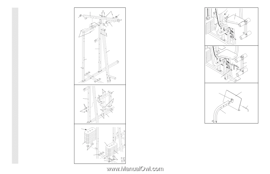
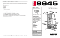
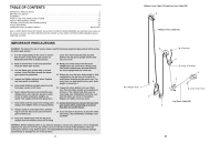
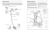
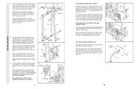
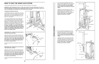
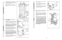
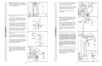
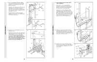
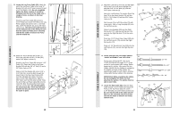
FRAME ASSEMBLY 4. Press a 2" Square Inner Cap (27) into the end 4 of the Top Frame (55). Press a 1 3/4" Square Inner Cap (44) into each end of the crossbar on the Top Frame. Press two 1" Round Inner Caps (49) into the top of the crossbar. 27 Attach the Top Frame (55) to the Assist Upright (74) and the Leg Press Upright (56) with two 5/16" x 2 3/4" Bolts (11) and two 5/16" Nylon Locknuts (3). Attach the Top Frame (55) to the Front 11 Upright (42) with two 5/16" x 2 3/4" Bolts (11), two 5/16" Flat Washers (8), and two 5/16" Nylon Locknuts (3). 55 11 49 8 44 3 44 Crossbar 3 56 42 74 5. Slide the Rear Seat Frame (100) onto the indicated 5/16" x 2 1/2" Carriage Bolts (1) in the Stabiliser (5). Hand-tighten two 5/16" Nylon Locknuts (3) onto the Carriage Bolts. Do not tighten the Nylon Locknuts yet. Attach the other end of the Rear Seat Frame (100) to the Leg Press Upright (56) with two 5/16" x 2 3/4" Bolts (11), two 5/16" Flat Washers (8), and two 5/16" Nylon Locknuts (3). Attach the Handle (82) to the Rear Seat Frame (100) with two 5/16" x 2 1/2" Carriage Bolts (1) and two 5/16" Nylon Locknuts (3). Tighten all Nylon Locknuts used in steps 1-5. 6. Set two Weight Bumpers (19) on the bracket on the Base (4) as shown. Set two Weight Bumpers (19) on the bracket on the Stabiliser (5). Stack ten Weights (25) onto the bracket on the Stabiliser (5). Stack eight Weights onto the bracket on the Base (4). Be sure that the pin grooves are all on the same side of each stack of Weights. Be careful not to tip either stack of Weights (25) until step 8 is complete. 6 5 56 8 3 6 Pin Grooves 1 100 11 3 3 1 82 5 25 25 19 5-Bracket 4-Bracket Pin Grooves 19 ATTACHING AND REMOVING THE SEAT To attach the Seat (13), set the bracket on the Front Seat Frame (36) onto the indicated pins on the Front Upright (42). Attach the Front Seat Frame to the Front Upright with the 5/16" x 2 3/4" Carriage Bolt (14) and the Seat Knob (40). For some exercises, the Seat (13) must be removed. First, be sure that the chain is not attached to the leg lever. Next, remove the Seat Knob (40) and the 5/16" x 2 3/4" Carriage Bolt (14) from the Seat Frame (36). Lift the Front Seat Frame off the Front Upright (42). ATTACHING THE LEG LEVER TO THE LOW PULLEY STATION To use the Leg Lever (29), the seat must be attached to the front upright (see ATTACHING AND REMOVING THE SEAT above). Attach one end of the Chain (52) to the Short Cable (23) with a Cable Clip (53). Attach the other end of the Chain to the Eyebolt (35) with a Cable Clip. ADJUSTING THE LEG PRESS PLATE Remove the Press Pin (97) from the Leg Press Plate (95) and the Leg Press Arm (96). Align the welded tubes on the Leg Press Plate (95) with the desired set of holes in the Leg Press Arm (96). Re-insert the Press Pin (97) through the welded tubes on Leg Press Plate and the holes in the Leg Press Arm. 40 36 13 42 14 53 52 29 35 53 23 Welded Tube 96 95 97 23
-
 1
1 -
 2
2 -
 3
3 -
 4
4 -
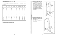 5
5 -
 6
6 -
 7
7 -
 8
8 -
 9
9 -
 10
10 -
 11
11 -
 12
12 -
13
-
14
-
15
-
16
-
17
-
18
-
19
 |
 |